General Structure of CFC Printed Composites

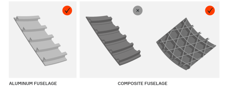
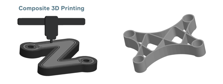
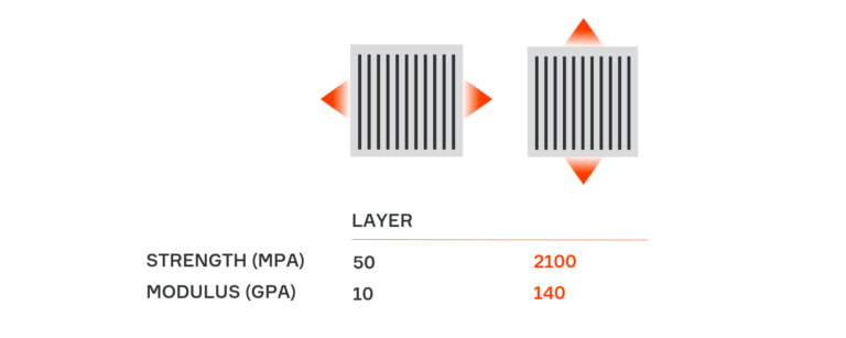
As in Fused Filament Fabrication (FFF), parts made by Composite Filament Co-extrusion (CFC) process are layered structures. Parts printed by Composer consist of flat reinforced layers.

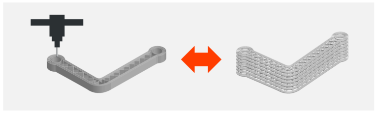
This means that the CFC printed parts can effectively carry loads acting in planes parallel to buildplate surface. Thus, you need to design the part in such a way that all reinforced layers become parallel to the loading plane. At the same time, the loading plane should be parallel to the buildplate surface when you print the part.

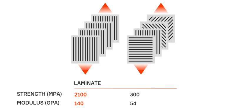
We do not recommend to manufacture very high parts by CFC printing. The high parts do not possess high strength in Z direction and can be broken under interlaminar loads. Recommended height of CFC printed part should not exceed the minimum overall dimension of the part in XY plane. If you plan to print part with big height, do it just by FFF printing.

Understanding Composites

Anisoprint technology is intended to produce lightweight, stiff and strong composite parts. Understanding composites is crucially important to extract maximal profit from the technology. Therefore, we wrote this guide to share our vision of composites and to assist you in understanding of these awesome materials.

Stop Metal Thinking

In conclusion of this guide, we would like to make a very important point. Composites are completely different from conventional materials (metals, plastics etc.). They are significantly anisotropic and inhomogeneous. This means that a metal (plastic) part and a composite part having the same purpose have to possess completely different designs! If you want to substitute a metal part with a composite part you should redesign one.

Note

Never adopt a metal driven design for composite parts!

Stop metal thinking – start Anisoprinting 😉

3D Printing of Composites

Currently, only 3D printing allows to obtain composite parts with complex shape and high flexible fiber reinforcing paths. With 3D printing you can control anisotropy and utilize potential of fiber reinforcement with maximum efficiency. By the way, that’s why we are called Anisoprint (anisotropic printing or printing with control of anisotropy). You do not need to cut fibers. You can manufacture any hole in composite part without drilling and with reinforcement. Moreover, Anisoprint technology (Composite Fiber Coextrusion) uses thermoplastic matrix that increases impact resistance of a part in contrast to conventional thermosetting composites.

Lattice Structures. Advantages and Restrictions

The most effective way to utilize potential of fiber reinforcement is lattice anisogrid structures. The peculiarity of the structures provides an effective distribution of loads along the fibers because the major acting loads run along the grid ribs i.e. in fiber direction. Thus, lattice anisogrid structures possess high weight efficiency in contrast to laminates.

The lattice structures are not afraid of cutouts and do not need drilling and milling. For these structures you can use special inserts.

Conventional composite technologies (winding, fiber placement) can produce parts only with geodesic and quasi-geodesic reinforcement paths, and regular grids. Structures with irregular grid density and non-geodesic reinforcement could provide more efficient distribution of acting loads and, as a result, weight reduction. However, such structures cannot be obtained by the conventional technologies.

Machining of Composites

If you need to joint composites or make some kind of hatch in a composite structural element, you will encounter the fact that you need to drill, mill or cut the composite material. Drilling, milling and cutting significantly reduce strength of reinforced composite in vicinity of the machined edge. The strength can drop down several times! So, the machining is actually killing the idea of reinforced composites application.

Note

Avoid drilling, milling and cutting reinforced composites! They do not like it!

Laminates and Their Properties

At the same time, reinforced composites have rather low properties in transverse direction.

Note

The observed difference in properties in different directions is called anisotropy.

Laminates with different stacking of composite layers are commonly used to counter this weakness. In such structures, layers with different orientations are designed to carry various acting loads.

This is the most popular, but not really good way to produce composite structures. Effective properties of the laminated composite are much less than the properties of the unidirectional composite in fiber direction.

Applications of Composite Materials

Reinforced composites have high stiffness and strength in the fiber direction and they are also lightweight. Therefore, there is a growing interest in such structural materials in aerospace, automotive, shipbuilding industries where weight plays a paramount role.

Note

Composites are very stiff and strong and at the same time are lightweight materials.

Composite Materials. Structural Composites

Composite materials (composites) consist of several components with different properties and distinct boundaries between the components. The composites can be “filled” with some particles or short/chopped fibers or “reinforced” with long (endless or continuous) fibers. A matrix is a material that bonds the fibers together or is filled with short fibers. Typically, the matrix has much lower mechanical properties than the fibers.

Note

Only composites with long (or continuous) fibers are actually structural materials because only long fibers provide high stiffness and strength!

So, further we will talk mainly about continuous fiber composites.

Structural Materials

Structural materials provide sufficient stiffness and strength. These characteristics allow a structure to maintain its shape and dimensions under loading or any other external action.

Typical structural materials are steel, aluminum, titanium alloys, concrete and some other. In addition, some composites are also structural materials.