Incorrect position of cutter

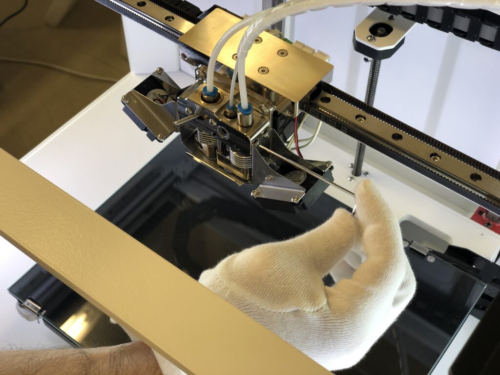
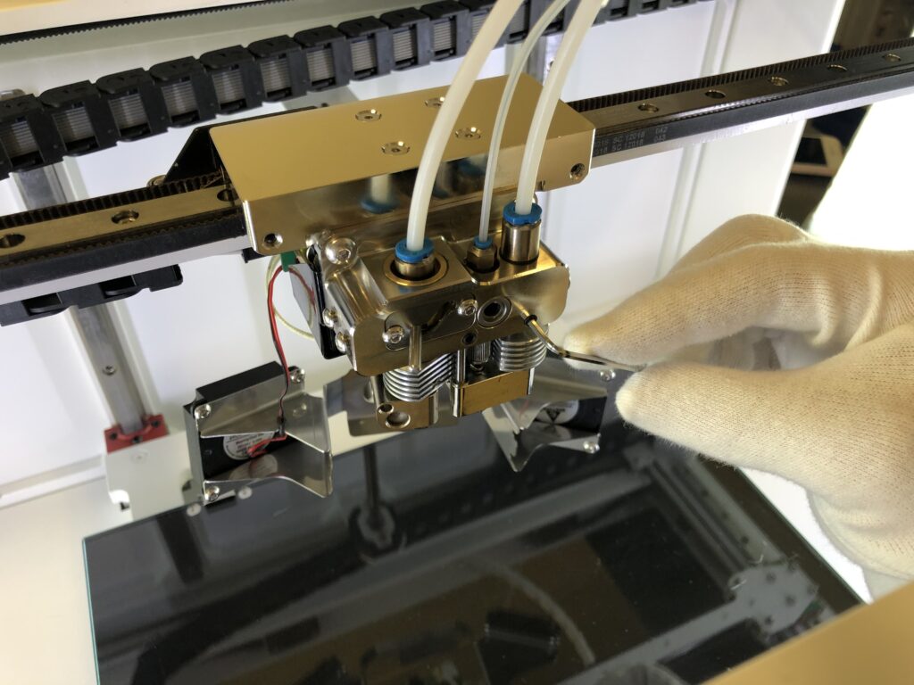
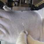
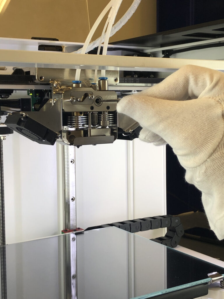
For the printer to operate properly, the cutter should be in a certain position. For some reasons (improper transportation, loose cutter bolt, etc.), the cutter may not be positioned correctly. To make sure the cutter is in the right position, go through the manual cutting procedure using Menu > Maintenance > Move > Extruders > “Scissors” button. If you cannot cut composite fiber, you should go through the cutter positioning procedure, described below.

CAUTION: while the printer is switched on, the servo is under voltage permanently, so if you try to tighten it with too much force it can lead to burning of the servo, please be careful and follow the instructions.


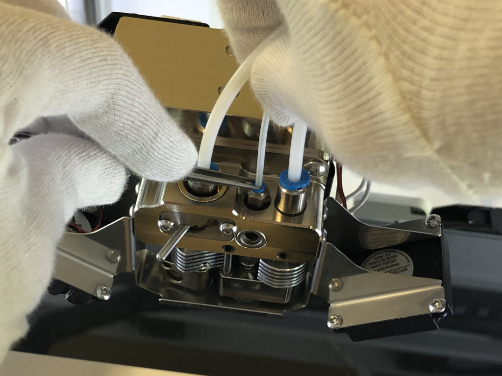
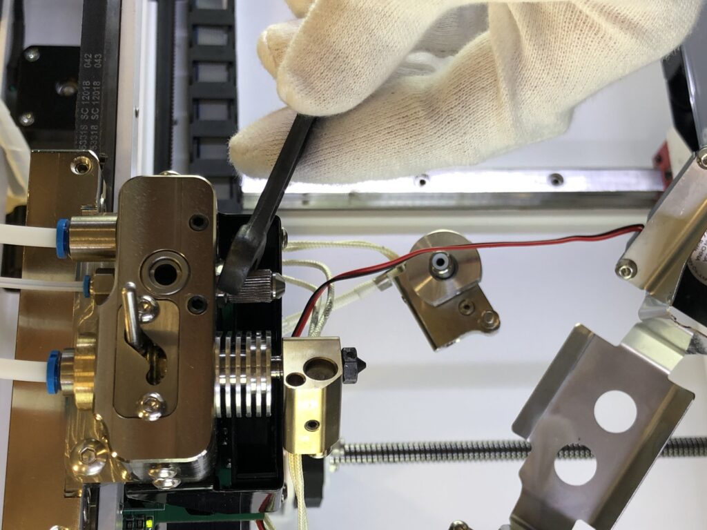
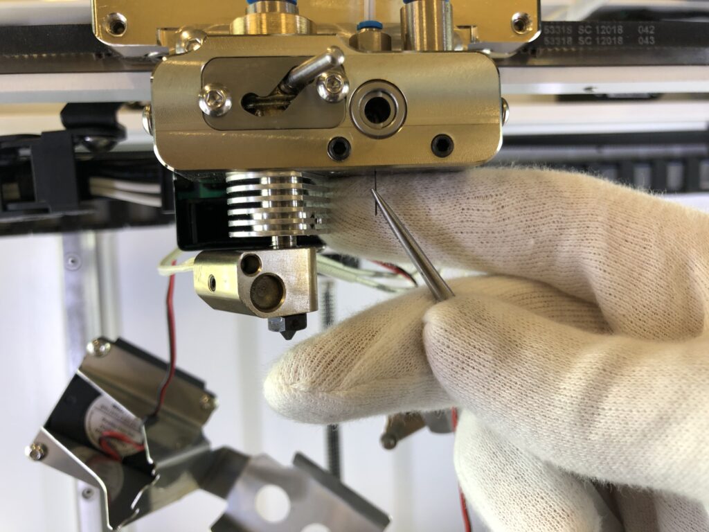
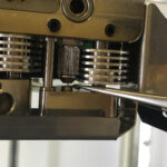
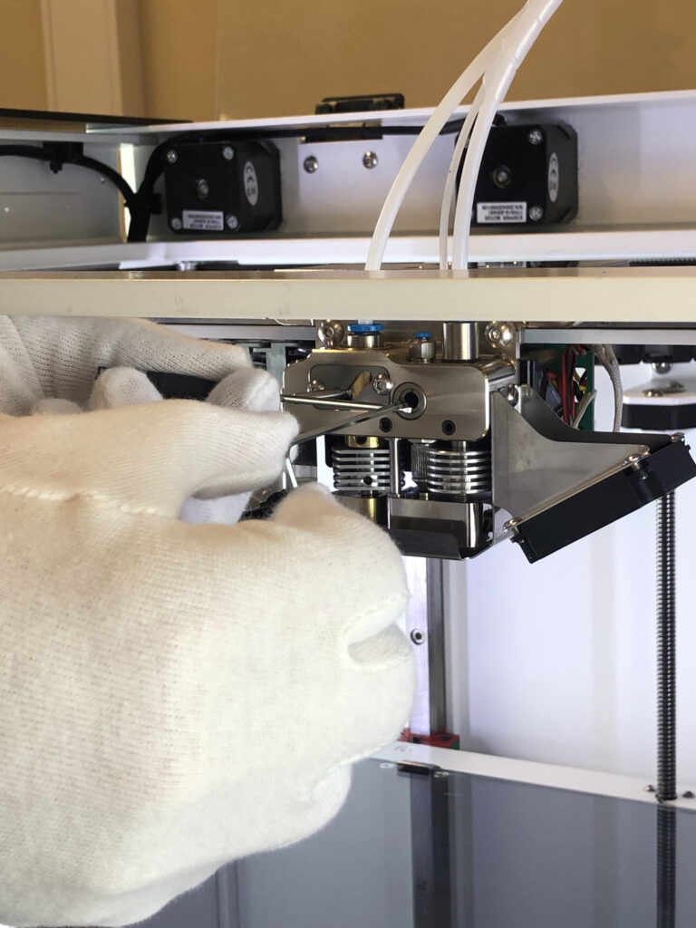
  1. Using the 2mm hex key from the Tool kit, loosen the bolt that fixes the cutter on the servo`s shaft.
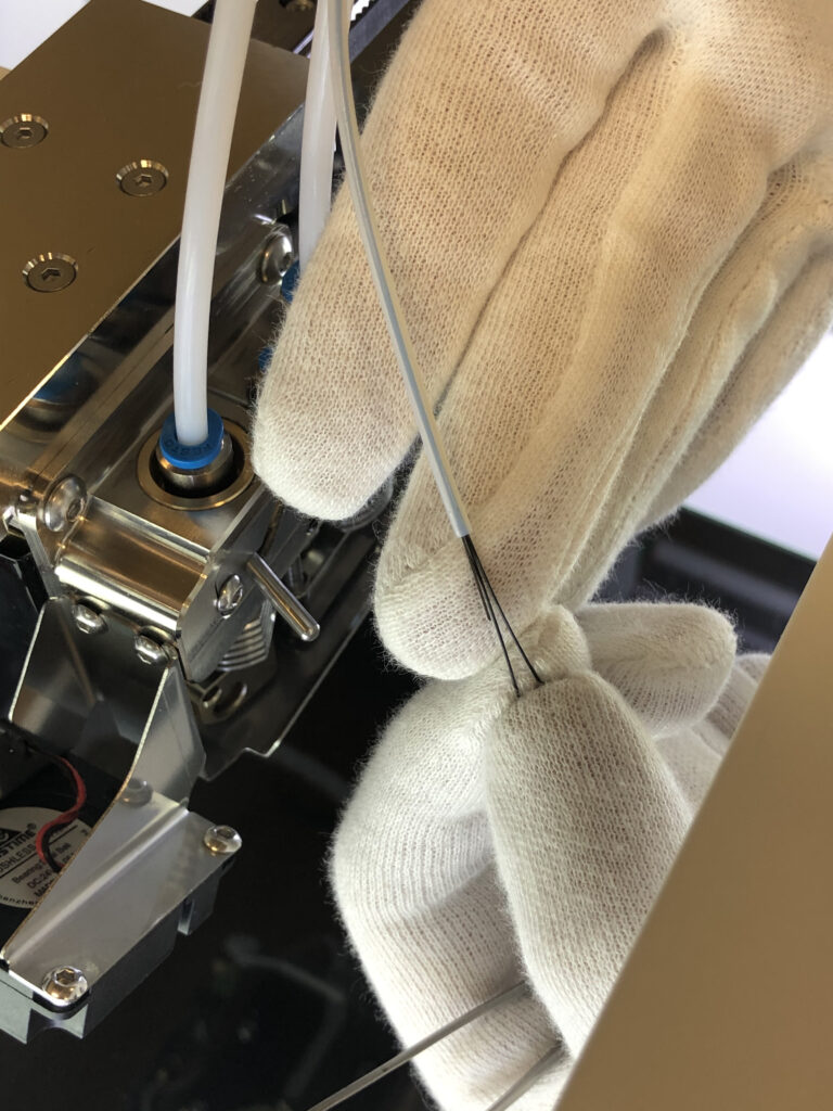
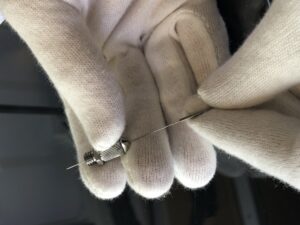
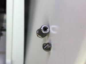
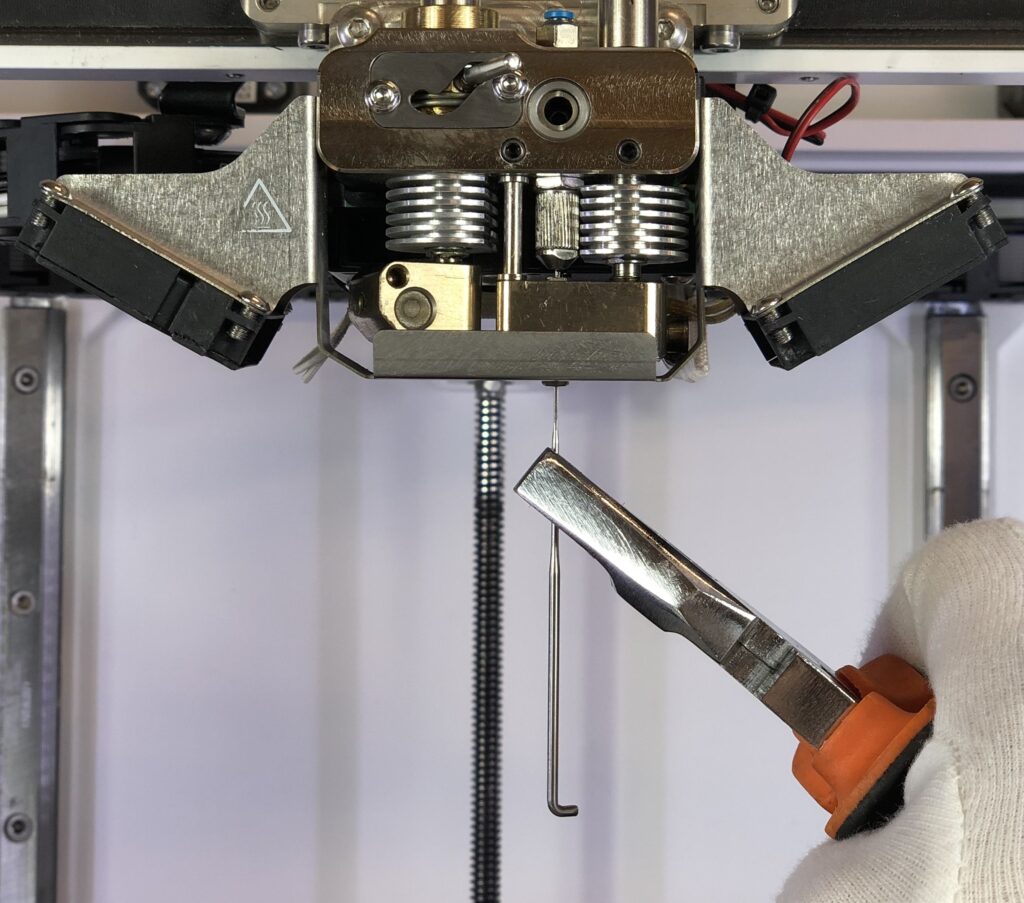
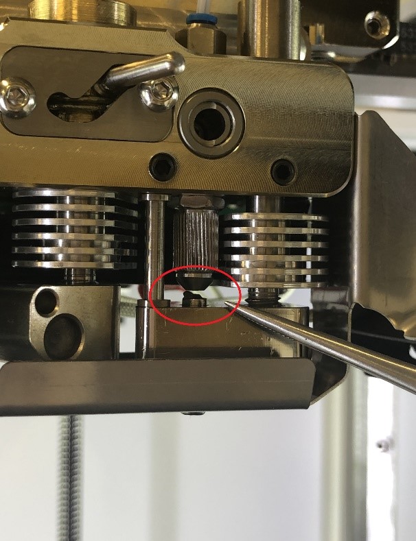
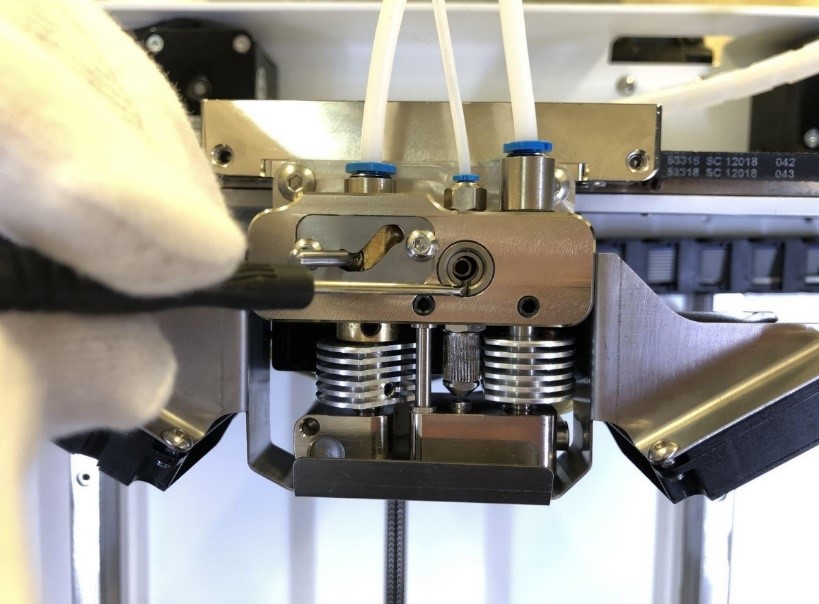
  2. Using a screwdriver or tweezers from the Tool kit place the shaft by rotation so the slot is in vertical position (for the first type of the cutter, see left picture below)/align the grooves on the cutter and sleeve (for the second type of the cutter, see right picture below) and then slightly fix the bolt.
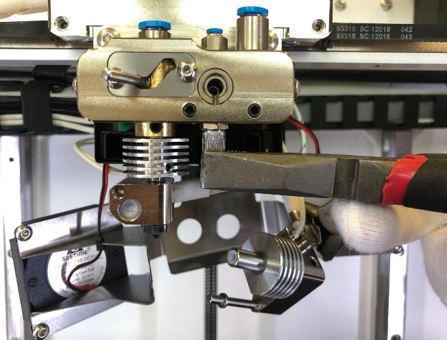
  3. Turn off the Composer and tighten the bolt. While tightening servo will rotate to its max angle and stop so you can tighten it.
  4. Turn on the Composer – servo will set on its “Zero angle”.
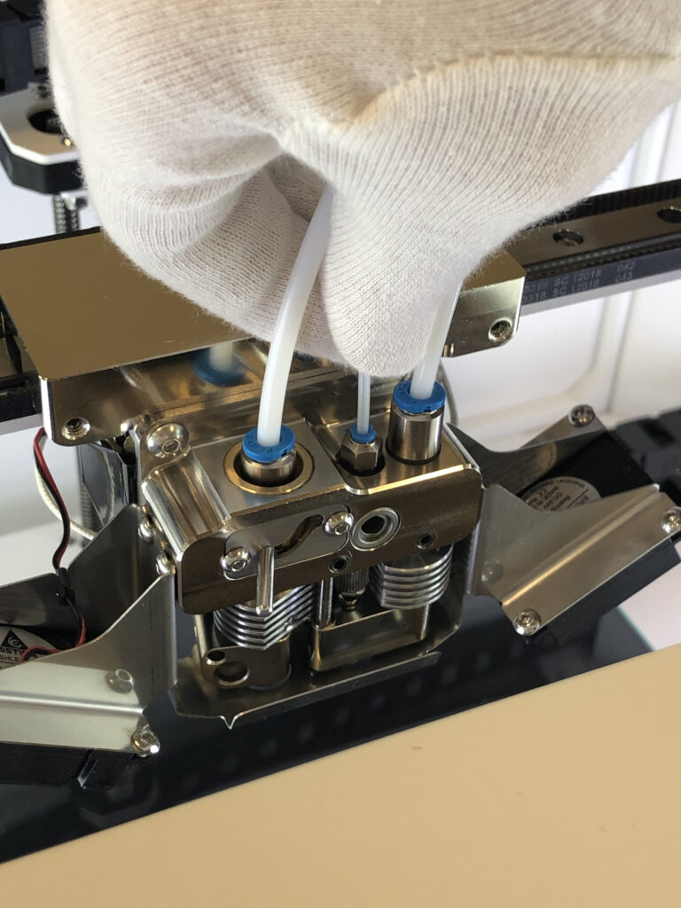
  5. Make sure that the top hole of the cutter sleeve is completely open and the cutter is firmly fixed. To check it, do the manual cutting procedure from the main menu or run NozzleOffsetTest.gcode from the external memory device supplied with your Composer printer. You can also download it from support.anisoprint.com.

Fiber is clogged inside the cutter

  1. Heat composite extruder up to composite plastic printing temperature (or a bit higher). On the main screen press the Composite extruder temperature button and set the required temperature (see point 1. from COMPOSITE EXTRUDER CHANNEL CLEANING, p. 8.3).
  2. Using the 2mm hex key from the Tool Kit loosen the side screws of the fan bracket. Remove the fan bracket carefully, the fan bracket stays hang on wires.
  3. Using the 2mm hex key from the Tool kit, loosen 2 set screws on the front of the extruder. Remove the composite extruder by pulling it down. Be careful, composite extruder stays hot so it can melt wires of the fan bracket.
  4. Using the wrench key or pliers unscrew the fiber guiding bushing.
  5. Check for the broken fibers inside the fiber guiding bushing.
    5.1 If the fiber is clogged inside the fiber guiding bushing, clean it with a needle from the set of cleaning tools, by pushing the fiber out of the bushing.
    NOTICE: fiber guiding bushing consists of two parts. If you face any problems while cleaning the channel, you can disassemble it and clean the parts separately.

  6. Using tweezers from the Tool kit remove clogged fiber from the cutter.
  7. Assemble the extruder in reverse order.

Fiber is clogged inside the composite extruder

For some reasons (incorrect printing parameters or improper maintenance), composite fiber may stop feeding, i.e stop coming out of the heat block. It means that composite fiber is clogged inside the extruder. For this case, a cleaning procedure is described below.

  1. Heat composite extruder up to composite plastic printing temperature (or a bit higher). On the main screen, press the Composite extruder temperature button and set required temperature (see point 1. from COMPOSITE EXTRUDER CHANNEL CLEANING, p. 8.3).
  2. If there are some fibers, sticking out of the heat block, remove them, by pulling down with tweezers.
  3. Clean the contact surface of the composite nozzle by brass wire brush from the set of cleaning tools (see point 2. from COMPOSITE EXTRUDER CHANNEL CLEANING, p. 8.3).
  4. Insert the barbed needle from the set of cleaning tools into the composite nozzle. Spinning the needle, push it through the extruder, until the end of the needle is in the inlet hole of the extruder. Be careful not to break the needle. Pull the needle down
    and clean it by tweezers so the barbs are clean. You may need to push/pull the needle with effort if the fiber is clogged tight, use pliers for this purpose.
  5. Remove material, pushed out of the inlet of the extruder with tweezers.
  6. Repeat points 4. – 5. until the needle is clean and the remains of the material stop pushing out of the inlet hole of the extruder.
  7. From the main screen go to Maintenance > Move > Extruders, change Step to 10 mm and feed 50 mm of the composite plastic filament (press V+ button 5 times). You should see clean plastic, exiting from the nozzle and inlet.

Plastic leaks out of the composite heat block inlet

There are several issues that may cause plastic leakage. If such an issue occurs, heat the composite extruder and remove plastic, leaked out of the heat block inlet with tweezers. Before this procedure, cancel the active print if there is one.

After the leaked out plastic is removed, go through the issue identification procedure described below:

  1. Check Z axis calibration. Incorrect Z axis calibration may cause plastic leakage on the inlet of the composite heat block. Go through Z AXIS CALIBRATION procedure, p. 7.5.
  2. Check Z offset calibration. Low Z offset value may cause accumulation of composite plastic inside the heat block and further leakage from the inlet. Go through Z OFFSET CALIBRATION procedure, p. 7.6.
  3. Check whether the composite plastic was dried before printing. The presence of moisture in filament will cause boiling of theliquid during printing, which will result in an uneven supply of composite plastic. Dry plastics in accordance with the material
    specification if required.

NOTICE: lack of composite fiber in the heat block or stop of its feed can cause plastic leak of the composite heat block inlet. This can happen during the composite plastic loading or its manual feed. The plastic fills the heat block and goes out through both the nozzle and the inlet simultaneously.

Strings and poor surface quality of printed part

There are some issues that may cause poor quality of the final part, including plastic under-extrusion, plastic stringing etc.

  1. Check whether the plastic was dried before printing. Most plastics tend to absorb moisture that affects the quality of the printed part. Dry plastics in accordance with the material specification if required.
  2. Check the nozzle surface cleanliness. Clean the nozzle by brass brush from the tool kit if required (see PLASTIC NOZZLE CLEANING, p. 8.2).
  3. If points 1. and 2. are met, then the nozzle is worn out. Long-term operation of the nozzle may cause wear that manifests in strips, gallings, or roughness of the inner surface of the nozzle, so you may need to replace the nozzle. Go through the PLASTIC NOZZLE REPLACEMENT procedure, p. 8.1 if required.