
1.Operation
1.1.Load/unload materials
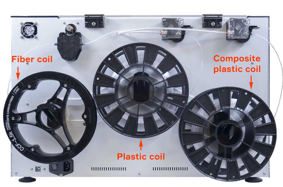
Composer A4 uses three spool: two of them are common 3D printing filament plastics, and the third one is Anisoprint Fiber.
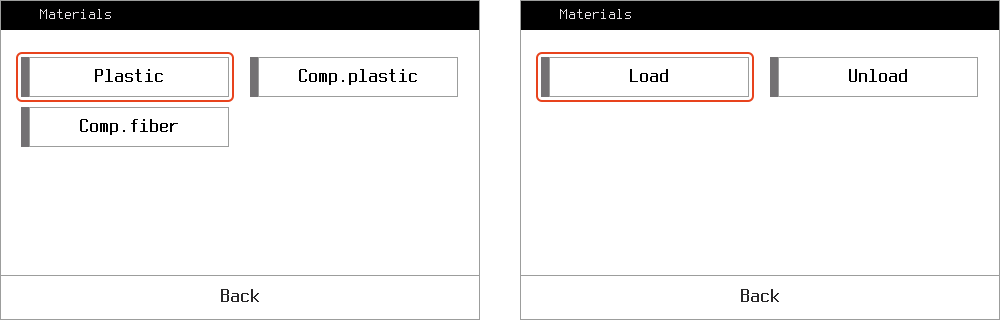
To load or unload a material you need to press Maintenance > Materials and choose a material spool you want to operate with. Choose load or unload an follow the automatic procedure instructions.
For every material, an extruder must be heated before operation. You can preheat the extruders to speedup the proccess.
The load/unload procedure is split into three steps: on the first step a feeder captures filament and you confirm it through the menu. On the second, stepper motor works at high rate, pushing material to extruder. On the third step, filament is gently transferred to hotend on a lower speed, and you need to confirm the material comes out of the nozzle.
For composite fiber there is a 4th step – you need to remove the cut fiber out of the nozzle using tweezers.
In some cases you might want to just move a material in/out of an extruder. In this case use Movement option as described here.
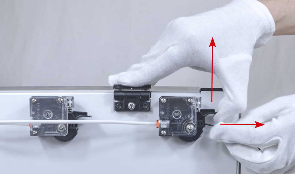
Another trick is a manual unload of plastic filament. When extruder is heated enough to release the filament inside, just release the clamp of the feeder and pull the filament out.
1.2.Heating and cooling extruders
On the Main Screen, press the extruder you want to heat and set the desired temperature using the arrows as shown below. Press Set button to start the heating proccess.
Caution!
The extruders and other parts of the printhead can be extremely hot!
Usually, the value you choose is the work temperature of the loaded plastic.
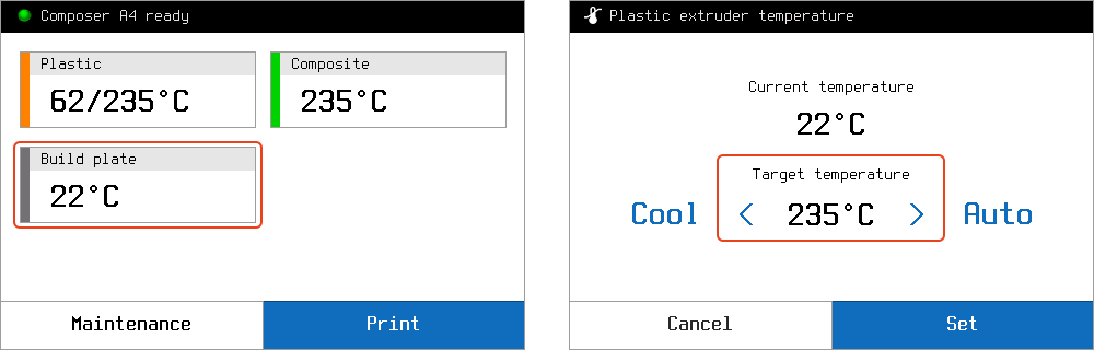
The Auto button allows you to choose the last temperature used for this extruder. Press Set to start heating.
The Cool button sets the room temperature for this extruder.
1.3.Printhead and extruders operation
You can move the printhead of your Composer to any point in the build area. To do this, on the Main Screen press Maintenance > Move. Choose a move distance and press axis arrows to move.
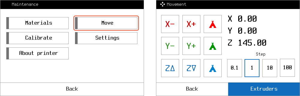
To move a filament back or forward, press Maintenance > Move > Extruders, choose a move distance and use extruder arrows to move. E stands for plastic filament in the plastic extruder, U and V for composite fiber and composite plastic respectively.
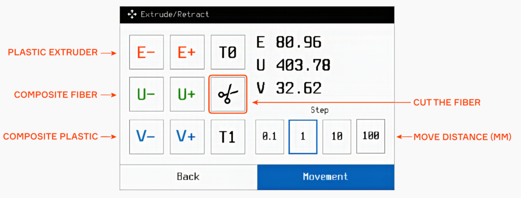
You can also cut the fiber by pressing the Scissors icon.
2.Calibration
2.1.Buildplate calibration
You may need to go through calibration procedure every time you replace a nozzle or after any other changes affecting relative positioning of the printhead and the buildplate, e.g. shaking or moving the printer. While printing a large part occupying the whole buildplate area, you can notice layer thickness varies from one end of the part to another, which as well means the buildplate requires recalibration.
Caution!
It’s highly recommended to preheat plastic nozzle before calibration as described here.
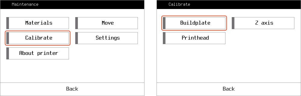
To start calibration, on the main screen press Maintenance. Choose Calibrate > Buildplate. Follow instructions. First, you will be asked to set the plastic nozzle in approximately 1 mm from the buildplate. The first of 3 points is to be set through the calibration menu, and the left and right corners are tuned manually by adjusting the regulation screws. Second, the procedure is to be repeated for fine tuning, this time using a sheet of an office paper to set the lowest possible gap between the nozzle and the buildplate. The paper must be sliding in the gap with a slight friction. Setting insufficiently low gap will lead to failed prints and printer malfunction.
It is recommended to calibrate Z axis right after buildplate calibration.
2.2.Z axis calibration
The distance between buildplate and plastic nozzle tip is quite an important parameter affecting the quality of your prints. If it seems that plastic layers are too thin or too thick, nozzle tip scratches buildplate or previous layers or the quality of vertical walls of your model is insufficient due to improper plastic layup, try this procedure.
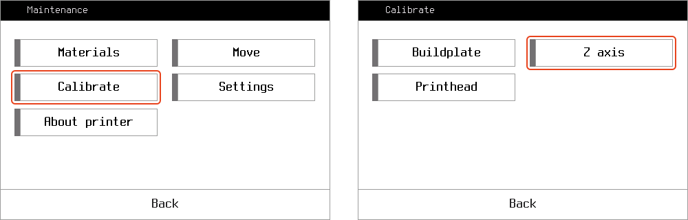
Press Maintenance > Calibrate > Z axis and follow the instructions. You will be asked to use a thin paper sheet to fine tune the gap between the nozzle tip and the buildplate.
Print any code to verify the results of the calibration, paying attention to brim and first layer layup.
2.3.Z offset calibration
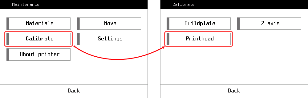
This procedure is critical for obtaining quality prints with continuous fiber. The basic procedure is automated in the printer menu. Go to printer Maintenance menu and hit Calibrate – Printhead.
Choose Comp. Z-offset button and follow the instructions on the screen. It is important to understand, that composite Z-offset value is measured relative to Z axis position – it is just a distance between plastic and composite nozzles tips on Z. It means that this calibration always must be done after Z axis calibration.
The full calibration sequence is also shown in our education video. But how can you determine you need this calibration in the first place? This is simple: at every composite print start, you will see a calibration fiber line printed at the front edge of the buildplate.
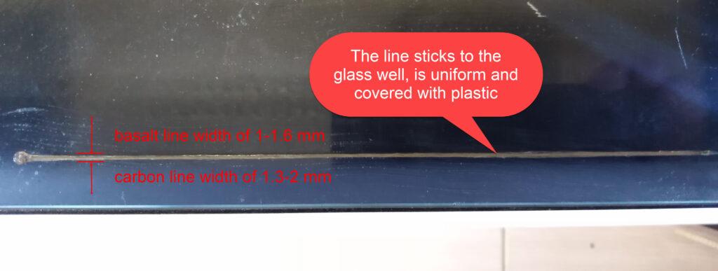
If you see the line is to high above the glass and doesn’t stick, it means the composite nozzle is too high, so the offset needs some adjustment. If the line is too wide, or the nozzle scratches the glass so the fiber cannot go out, it means the nozzle is too low.
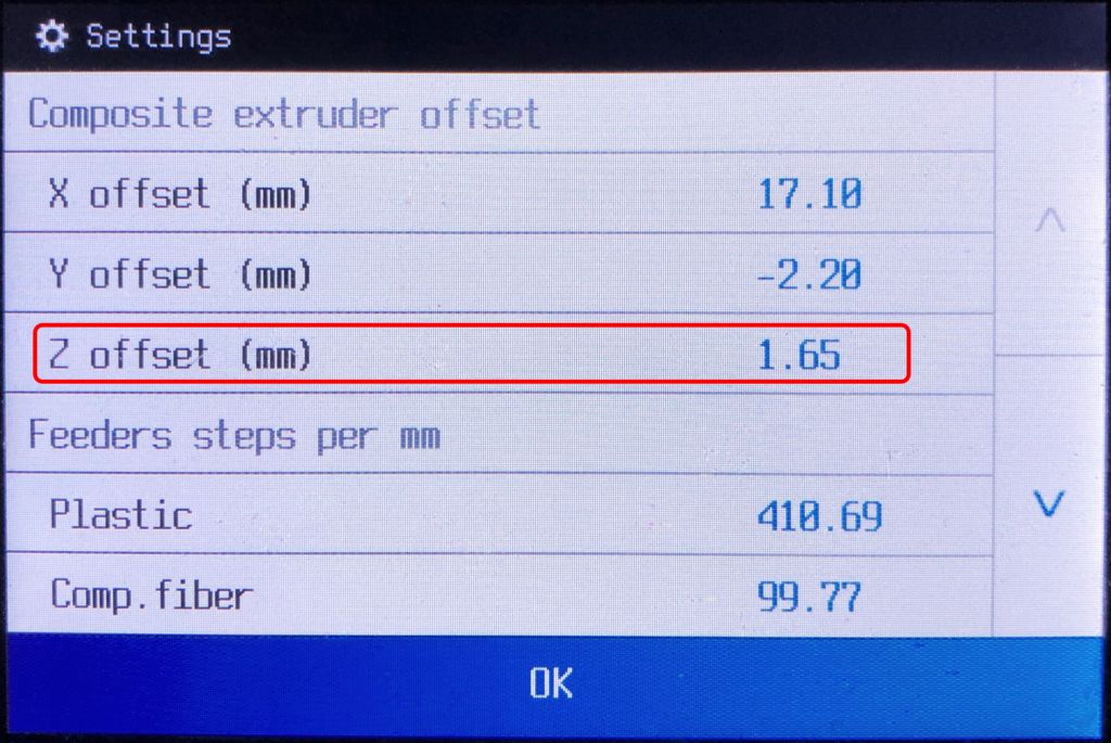
After calibration is done, you might want to check yourself with offset value in Settings. Typical values for z-offset will lie within 1.6-2.3 mm.
2.4.XY offset calibration
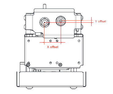
X and Y offsets are the physical distances between the tips of the plastic and the composite nozzles at the Composer print head, shown in the picture below.
You need to go through XY offsets calibration once after composite or/and plastic nozzle replacement. In order to calibrate XY offsets, print the special service code NozzleOffsetTest.gcode from the external memory device supplied with your Composer printer. You can also download it from support.anisoprint.com
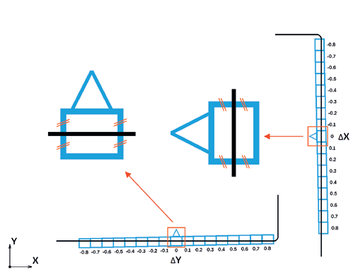
If the XY offsets are well-calibrated, the composite fiber is in the middle of the central cells, like it is shown in the scheme
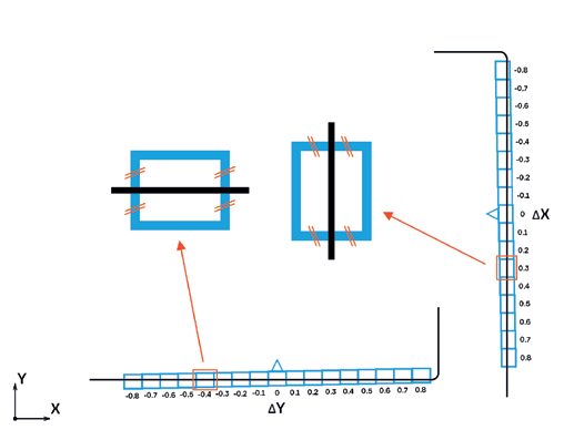
If the composite fiber deviates from the middle position of the central cells, like it is shown in the reference scheme, you need to change your XY offsets values (i.e calibrate it)
In order to calibrate XY offsets, for every axis find the cell where the composite fiber is right in the middle as shown on the reference scheme (right picture). XY adjustment value for each axis is written near the corresponding cell. For the given example it is +0.3 for X offset and -0.4 for Y offset, which means that you need to add +0.3 to the original X offset and -0.4 to the original Y offset.
To change these values, go to Maintenance > Settings.
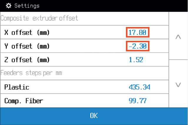
The new offsets will be
17.80 + 0.30 = 18.10 for X offset,
and -2.30 – 0.40 = -2.70 for Y offset.
After adjusting the offsets, reprint the offset test and make sure that composite fiber is in the middle position for both X and Y central cells.
3.Print Head
3.1.Plastic nozzle replacement
You might need to clean the inner surface of a nozzle – chemically or mechanically, for that, you need to remove the nozzle and install it again. Here are the steps.
- Using the 2mm hex key from the tool kit, loosen the side screws of the fan bracket. Remove the fan bracket carefully, it should hang on wires.
- Heat the plastic extruder to the printing temperature (270 °C for Smooth PA).
- Using the 7 mm socket wrench, unscrew the plastic nozzle from the plastic extruder, do not use too much force to avoid damaging the nozzle.
- Clean the nozzle or use a new one.
- The nozzle is installed with a special copper washer to avoid leakages of plastic from the extruder. Be sure to remove it from the old nozzle and install on the threaded end of the new one.
![]()
CAUTION: all extruder part can be hot!
3.2.Plastic nozzle cleaning
You might need to clean the plastic nozzle, for instance – if the under-extrusion occurs. Follow the next steps to clean the plastic nozzle:
- Heat the plastic extruder to the printing temperature (270 °C for Smooth PA).
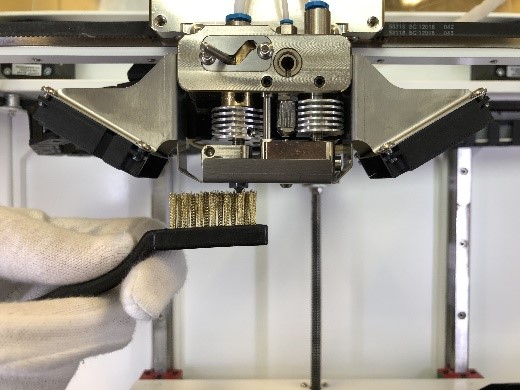
- Clean the nozzle with a cleaning needle from the tool kit. To clean the contact surface of the nozzle, use the brass brush from the tool kit.
3. To finish the cleaning, feed about 50mm of plastic to the extruder.
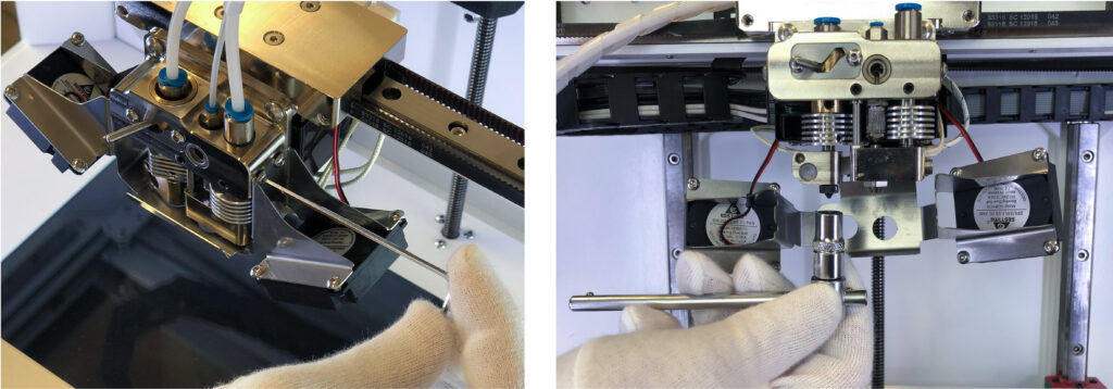
3.3.Composite extruder channel cleaning
To prevent fiber clogging the extruder cleaning is recommended before each print. This will ensure the successful printing of the parts without fiber clogging.
![]()
CAUTION: all extruder parts can be hot!
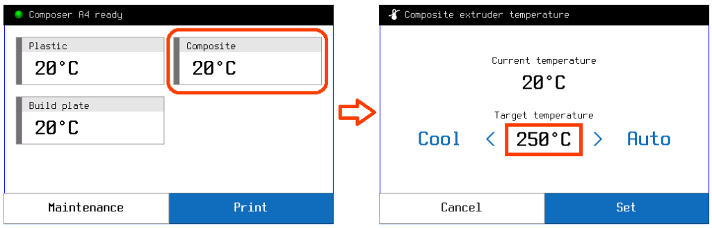
- Heat composite extruder up to composite plastic printing temperature (or a bit higher). On the main screen press Composite extruder temperature button and set required temperature.
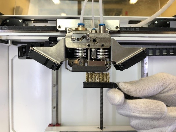
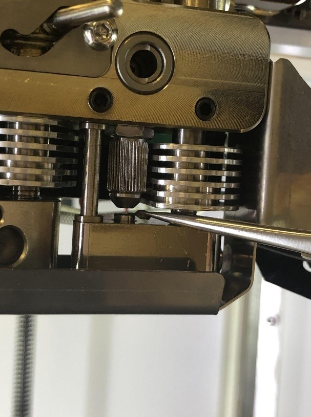
2. Clean the contact surface of the composite nozzle by brass brush from the set of cleaning tools.
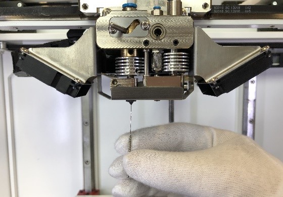
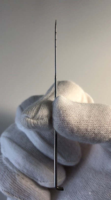
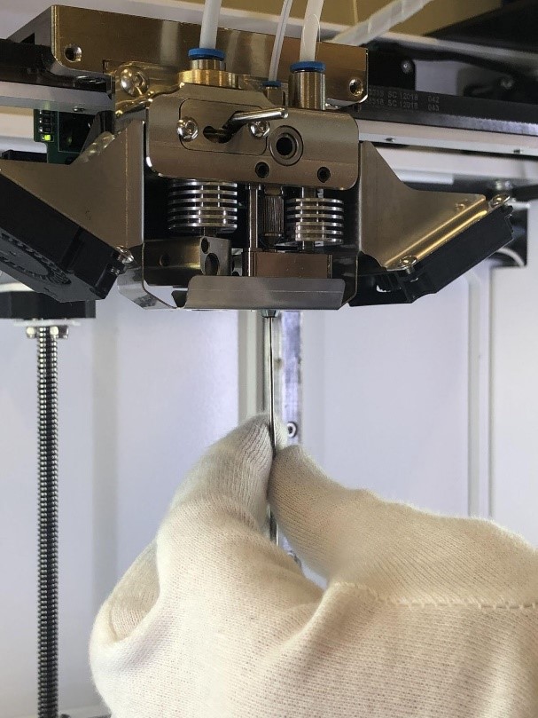
3. Insert the barbed needle from the set of cleaning tools into the composite nozzle. Spinning the needle, push it through the extruder, until the end of the needle is in the inlet hole of the extruder. Be careful not to break the needle. Pull the needle down and clean it by tweezers so the barbs are clean.
4. Remove material, pushed out of the inlet of the extruder with tweezers.
5. Repeat points 3. – 4. until the needle is clean and the remains of the material stop pushing out of the inlet of the extruder.
6. From the main screen go to Maintenance > Move > Extruders, change Step to 10 mm and feed 50 mm of the composite plastic filament (press V+ button 5 times). You should see clean plastic exiting from the nozzle and inlet.
4.Maintenance
4.1.Lubrication
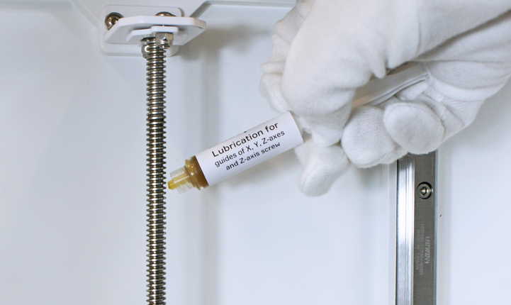
To extend the service life of the Composer CFC Printer, the mechanical parts of the product must be serviced periodically. The
service includes lubrication of moving nodes: guides of X, Y, Z-axes, Z-axis screw and plastic extruder. The delivery package includes
two types of lubricants: for the plastic nozzle and guide axes. lubrication of mechanical parts of the printer is recommended at least
once every six months.
5.Firmware
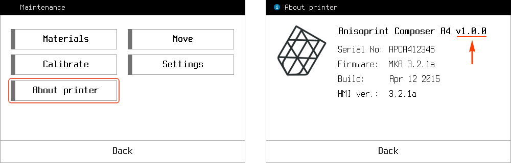
5.1.Hardware version
To find out the hardware version, press Maintenance > About printer
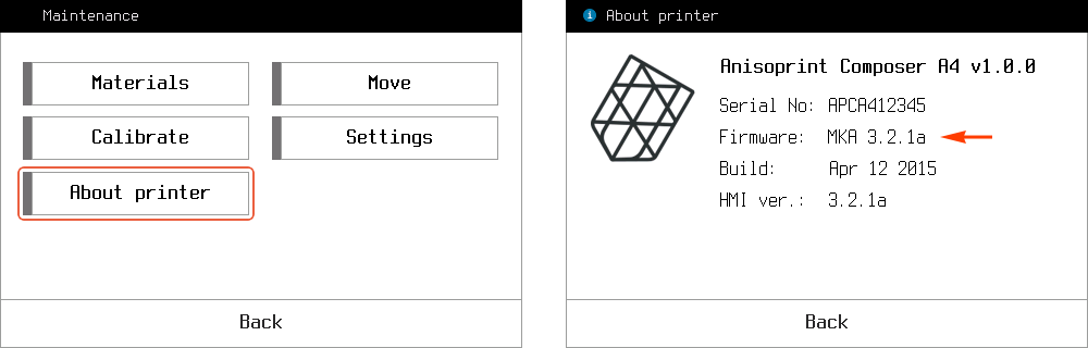
5.2.Firmware version
To find out the firmware version, press Maintenance > About printer
5.3.Composer firmware update
The latest Composer firmware can be downloaded here.
To update printer firmware you can use Anisoprint Aura. Install and launch Aura.
If you connect Composer to your PC for the first time you may need to install the USB driver. To install the driver unzip the archive and run dpinst-amd64.exe if you have 64-bit OS or dpinst-x86.exe if you have 32-bit OS.
Connect the printer to the PC by USB cable. In Aura main menu open Tools > Composer firmware update.
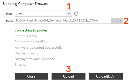
In Composer firmware update tool:
- In Port list select the COM port of Composer. If you connected Composer to your PC for the first time, it will usually be the last one. If the list is empty or you can’t connect to printer using any listed port, make sure, that you have installed SUB driver mentioned above.
- Click on “…” button near Path field and select Composer firmware file.
- Press Upload button.
- Wait until all lines including the last “Success” button become green.
Note
Do not disconnect or turn off your printer during firmware update process.