Test part “Wall bracket” introduces you to capabilities of your Composer A4 and also serves as a combined quality test. You can find the gcode for this test preloaded on your Composer SD, or download it from Anisoprint Support Portal / Printing tests page. Choose the code sliced for the particular filament you have.
- Use recommended adhesive for you plastic filament, e.g. Magigoo Original for transparent PETG, or Magigoo PA for Smooth™PA.
- After print start, both extruders, plastic and composite, start to heat. When composite extruder reaches extrusion temperature, composite nozzle will print a short purge line(composite thread) in front of the build plate. It must be glued to the surface and look smooth and uniform. At the end of printing the purge line you will hear a characteristic sound of the fiber cutter.
- After printing the purge line, the machine will start with the first plastic layer. Check if the plastic perimeters look the same everywhere along the part. The first layer must be nicely glued to the build plate. At the same time, wipe tower will be started on the left side of the build plate.
- After several plastic layers, the machine will go the first fiber perimeter and fiber cellular infill. Due to the process features, it may look a bit wobbly, but the layup visual quality will normalize later on. If the fiber goes off trajectory or doesn’t glue to the previous layer, check your Z-offset calibration.
- During the next plastic-composite cycles, fiber perimeters will be surrounded by plastic ones. Make sure the plastic and fiber perimeters do not intersect, and fiber perimeters are laid without displacements.
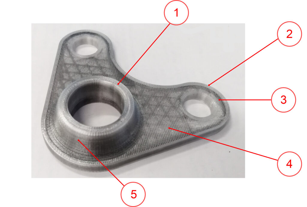
Inspect the printed part, paying special attention to side walls quality. Check the surface smoothness visually. The typical print quality will be similar to the photo below: