1.General Structure of CFC Printed Composites
As in Fused Filament Fabrication (FFF), parts made by Composite Filament Co-extrusion (CFC) process are layered structures. Parts printed by Composer consist of flat reinforced layers.
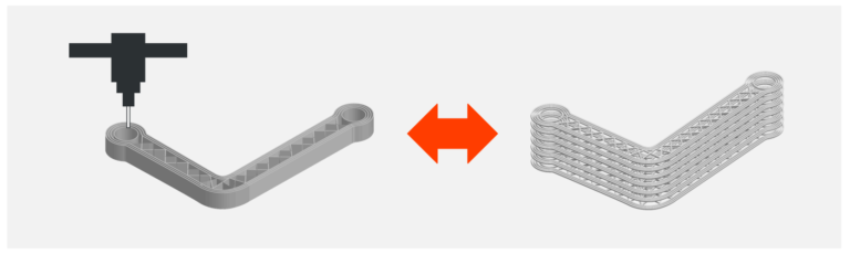
This means that the CFC printed parts can effectively carry loads acting in planes parallel to buildplate surface. Thus, you need to design the part in such a way that all reinforced layers become parallel to the loading plane. At the same time, the loading plane should be parallel to the buildplate surface when you print the part.
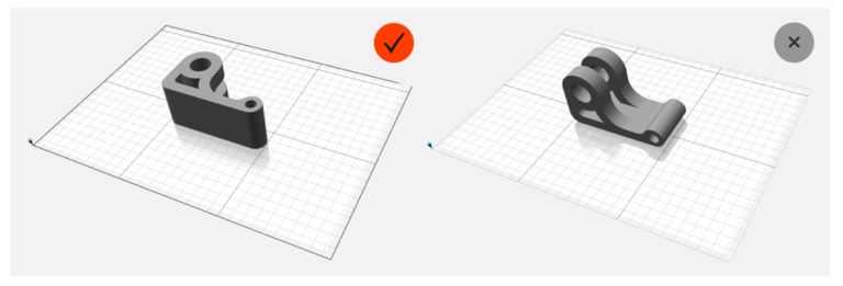
We do not recommend to manufacture very high parts by CFC printing. The high parts do not possess high strength in Z direction and can be broken under interlaminar loads. Recommended height of CFC printed part should not exceed the minimum overall dimension of the part in XY plane. If you plan to print part with big height, do it just by FFF printing.

2.Loaded Elements Suitable for Manufacturing on Composer
Elements under plane stress means rather thin parts that are subjected to in-plate loads and loads do not change through the part thickness. When out-of-plane loads for real thin parts are small and neglectable these parts can be considered as under plane stress. Manufacturing of such parts is the best way for application of CFC printing.
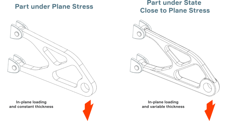
Elements under bending are also mostly subjected to in-plane loading. So, in contrast to plane stress state, acting stresses vary through the element thickness. The greatest stresses are close to the external surfaces of the part. In addition to in-plane stresses, interlaminar shear stresses accompany the bending in most of cases. Maximum interlaminar shear stress is close to central layers. As a rule, the interlaminar shear stress is much less than in-plane stresses and the smaller thickness-to-length ratio for the part the less interlaminar shear stress in comparison to in-plane stress.
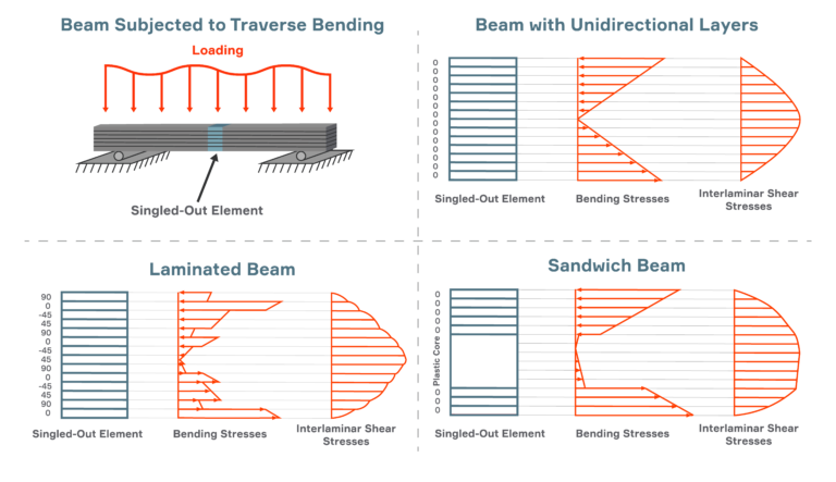
Examples of structural elements under the bending
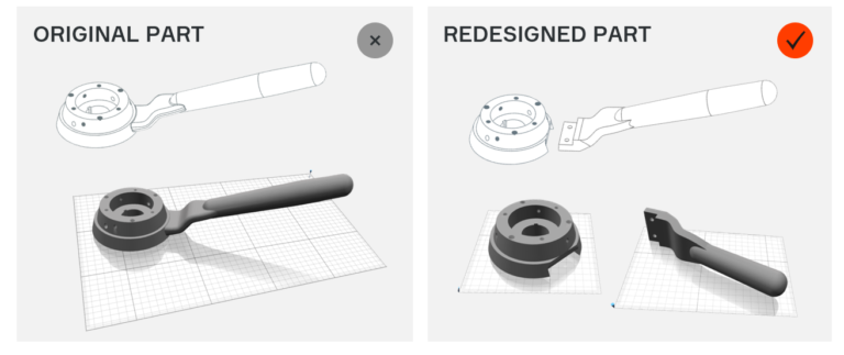
If a loaded structure is complicated and it does not directly comply with description above sometimes an engineer can split such structure on simple structural elements subjected to in-plane loading and the final structure will become an assembly.
3.Reinforcement with Aura
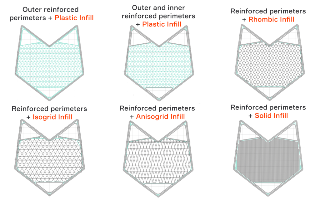
To help you with reinforcement of a part we developed slicer Aura. Aura algorithms are based on our intuitive vision of how composites should work. You can reinforce external and internal boundaries of each layer of the part with one or several fiber perimeters, so called outer and inner perimeters. You can also reinforce inner space of the part with solid (conventional laminate) or lattice patterns. Such reinforcement is called reinforced infill. Different layers or groups of layers can have different reinforcement.