
1.Plastic
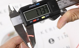
1.1.Filament diameter
The filament diameter of plastic thread is measured in cross section. Usually it is 1.75mm or 3mm. You can find this value on the package of plastic filament.
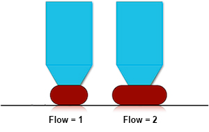
1.2.Flow multiplier
The flow multiplier is a correction factor of plastic extrusion. Vary this parameter if all parts have under- or overextrusion.
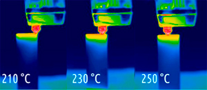
1.3.Extruder temperature (°C)
The extruder temperature is the temperature at which plastic will be melted for extruding from a nozzle. You can find an appropriate temperature range on the plastic filament package.
1.4.Standby extruder temperature (°C)
The standby extruder temperature is the extruder temperature at which it will be in an inactive state (another extruder is active, i.e. is printing). It should be as close as possible to printing temperature for faster heatup and print start, but low enough to prevent plastic free flow out from an extruder by gravity.
1.5.Build plate temperature (°C)
The build plate temperature is the constant temperature of a build plate throughout all printing process except printing first layers. Set this value high enough so a part won’t detache and edges won’t bend.
1.6.First layers temperatures height (mm)
The first layers temperatures height is the height below which extruders and a table have special heating rules.
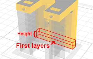
1.7.Extruder temperature on first layers (°C)
The extruder temperature on first layers is the extruder printing temperature which is kept constant only on first layers – below height defined in settings.
1.8.Build plate temperature on first layers (°C)
The build plate temperature on first layers is the table’s temperature which is kept constant only on first layers below height defined in settings. It should be high enough for a part immediately and securely glues to a table.
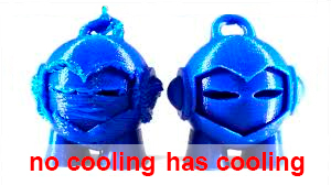
1.9.Enable print cooling
Enable print cooling is the flag of fan on/off for cooling extruders. For best results, turn on cooling with any print.
1.10.Regular fan speed (%)
The regular fan speed is the fan speed for cooling while all printing process except printing first layers. Indicated as percentage. Choose high enough for saving part geometry undisturbed, but not too high for layers start losing good adhesion beetwen themselves.
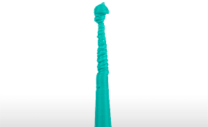
1.11.Maximum fan speed (%)
The maximum fan speed is the fan speed for cooling which is used when layer time is less than minimal layer printing time (specified in settings). Indicated as percentage. Choose maximum speed to have no form meltings and geometry distorsions.
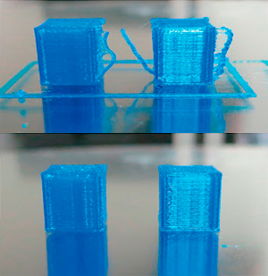
1.12.First layers fan speed height (mm)
The first layers fan speed height is the height below which cooling rules are special. Choose a minimum but sufficient height so a part is securely glued to a bed and part geometry won’t lose its geometry by bed heating.

1.13.First layers fan speed (%)
Choose the fan speed low enough for better adhesion to a bed and to prevent geometry changes due to bed heating.
1.14.Retraction length (mm)
The retraction length is the length of plastic reverse movement in a feeder. Choose long enough length to stop pressure onto plastic in an extruder chamber. Keep in mind that during retract, the extruder stays still, so the longer retract, the longer it stays without movement, which can lead to part melting by the extruder, and leakings for runny plastics.
1.15.Retraction length on tool change (mm)
The retraction length on tool change is the length of plastic reverse movement in a feeder. Choose maximum length, taking into account the fact that plastic won’t be fed into this tool for a long time and it is necessary to prevent plastic leakings due to gravity.
1.16.Retraction minimum travel (mm)
The retraction minimum travel is the sufficient travel length before retraction. In case of short travels it makes no sence to stop for retraction because plastic has not enough time to spill out uncontrolled. Choose this value to maximum, but beware of plastic leaks while travels.
1.17.Extra unretract length (mm)
The extra unretract length is the value additional to retract length. On print resuming, if portion of plastic has spilled from an extruder, then volume of plastic in a nozzle becomes less than what it was before travel. If you have noticed for this plastic (especcially for runny) that at the beginning of print there is an underextrusion migrating to normal extrusion, then you shoud set not null for this parameter.
1.18.Retract speed (mm/sec)
The retract speed is the speed of reverse movement of plastic in a feeder. Choose maximum for fast printing restart, however, keep in mind that some feeders can’t handle fast feeding speed.
1.19.Unretract speed (mm/sec)
The unretract speed is the speed of direct movement of plastic in a feeder. Choose maximum for fast printing restart, however, keep in mind that some feeders can’t handle fast feeding speed.
1.20.Z-hop height (mm)
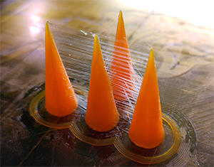
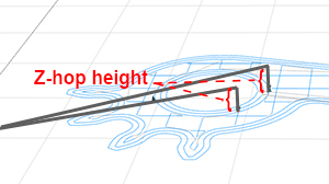
The Z-hop height is the extruder lift up height when moving between print areas. Choose minimum for fast printing process, but enough for prevent part edges hitting and as a result bringing and leaving beads on a part shell. Z-hop may lead formation of strings, however, it is usually easier remove this than removing beads.
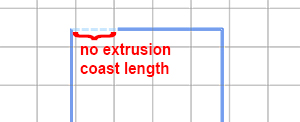
1.21.Coast length (mm)
The coast length is the length of the last polygon segment which is printed without plastic extrusion. Plastic goes out only by gravity on this coast segment. Choose length enough to stop free plastic spilling after retract, however, keep an eye on underextrusion.
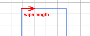
1.22.Wipe nozzle length (mm)
The wipe nozzle length is the length of reverse print head movement. The print head is moving in reverse after retract and is wiping spilling plastic on already printed lines. Choose length enough for stop free plastic spilling after retract.
2.Fiber
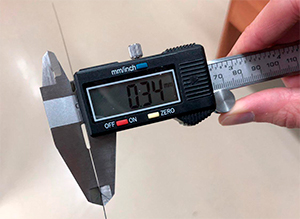
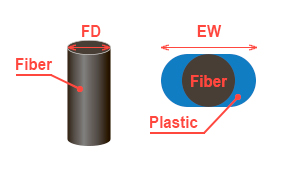
2.1.Fiber diameter (mm)
The fiber diameter is the average diameter of a fiber thread measured in cross section. For the Anisoprint CCF-1.5k this value is 0.34mm.
2.2.Plastic flow multiplier
The plastic flow multiplier is a factor by which amount of extruded plastic in a composite extruder is multiplied. Vary this parameter if all composite polygons have under- or overextrusion.
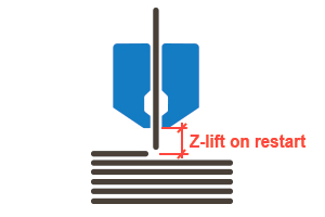
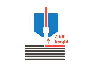
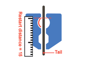
2.3.Z-lift on restart (mm)
Z-lift on restart is the height at which a composite extruder is raised to put out a fiber tail and start to print a composite polygon.
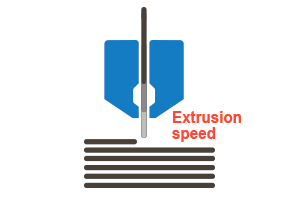
2.4.Fiber extrusion speed (mm/sec)
Fiber extrusion speed is the speed of the fiber tail extrusion.
2.5.Restart pause (sec)
Restart pause is the delay before start of composite polygon printing. This is needed for the good adhesion between a fiber tail and an a underlying layer.

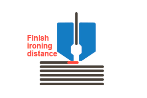
2.6.Finish ironing distance (mm)
Finish ironing distance is the length of travel which is performed by a composite nozzle at the end of fiber polygon in the direction of last segment. It happens after cut and full exit a of fiber tail. This movement is needed for ironing tail which, if not done, will be fluffy.
2.7.Do plastic retract
The do plastic retract flag is the flag which indicates that plastic retract should be performed during composite printing.
2.8.Linear density (tex = g/km)
Linear density is the mass of 1km of fiber in grams.
3.Printer
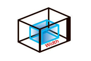
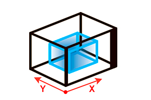
3.1.Width (mm)
The width is the size of build area along the X axis.
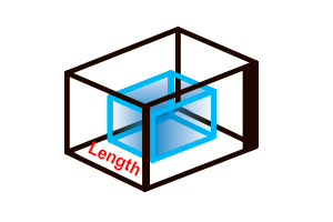
3.2.Length (mm)
The length is the size of build area along the Y axis.
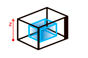
3.3.Height (mm)
The height is the size of build area along the Z axis.

3.4.X/Y travel speed (mm/sec)
The X/Y travel speed is the linear speed of print head movements in XY plane without extrusions.
3.5.Z travel speed (mm/sec)
The Z travel speed is the linear speed of print head movements in the Z direction without extrusion.
3.6.Enable acceleration control
The enable acceleration control is the flag of manual control over acceleartions.
3.7.External shell acceleration (mm/sec²)
The external shell acceleration is the acceleration which is used only for external shell printing. It has affect on travels and moves with extrusion.

3.8.Regular acceleartion (mm/sec²)
The regular acceleration is the acceleration which is used for all printing areas except an external shell. It has affect on travels and moves with extrusions.
3.9.Enable jerk control
The enable jerk control is the flag of manual control over jerks.
3.10.External shell jerk (mm/sec)
The external shell jerk is the jerk value which is used only for external shell printing. It has affect on travels and moves without extrusion.
3.11.Regular acceleartion (mm/sec²)
The regular jerk is the jerk which is used for all printing areas except an external shell. It has affect on travels and moves with extrusion.
3.12.Has heated build plate
The has heated table flag is the flag which indicates if a printer has heatable table.
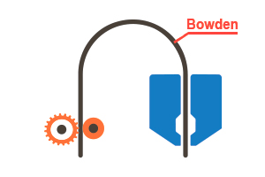
3.13.Additional retract length (mm)
The additional retract length is the additional length of plastic reverse movement in a feeder which will be added to the retract length value for used plastics. Use this parameter if your printer has bowden tube for plastic feeding, because in this case retraction inertia may appear.
3.14.Z-lift on tool change (mm)
The Z-lift on tool change is the height at which a print head raises for tool change.
3.15.Start G-code
The start G-code is the code which is executed at the start of print process.
3.16.End G-code
The end G-code is the code which is executed at the end of print process.
4.Extruder (Plastic)
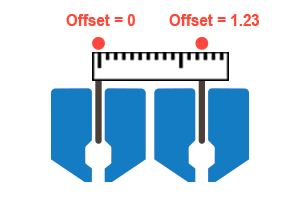
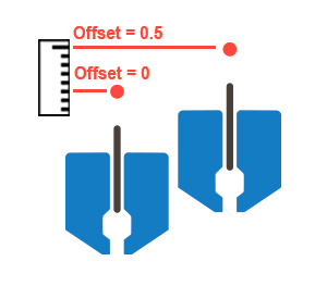
4.1.X offset (mm)
X offset is the extruder X offset relative to the base point on a print head. If your printer has only one extruder then set this parameter to zero. If printer firmware doesn’t set offset by itself then you should set other extruders offsets relative to base (usually first) extruder. In this case you sholud set offsets for this base extruder offsets to zero.
4.2.Y offset (mm)
Y offset is the extruder Y offset relatively to the base point on a print head. If your printer has only one extruder then set this parameter to zero. If printer firmware doesn’t set offset by itself then you should set other extruders offsets relative to base (usually first) extruder. In this case you sholud set offsets for this base extruder offsets to zero.

4.3.Z offset (mm)
Z offset is the extruder Z offset relatively to the base point on a print head. If your printer has only one extruder then set this parameter to zero. If printer firmware doesn’t set offset by itself then you should set other extruders offsets relative to base (usually first) extruder. In this case you sholud set offsets for this base extruder offsets to zero.

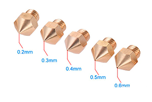
4.4.Nozzle diameter (mm)
The nozzle diameter is the diameter of the outlet hole of a nozzle.
4.5.Has cooling fan
The has cooling fan flag is the flag which indicates thar extruder has a nozzle cooling fan.
4.6.Cooling fan index
The cooling fan index is the number of this cooling fan in printer firmware.
5.Extruder (Composite)
5.1.X offset (mm)
X offset is the extruder X offset relative to the base point on a print head. If your printer has only one extruder then set this parameter to zero. If printer firmware doesn’t set offset by itself then you should set other extruders offsets relative to base (usually first) extruder. In this case you sholud set offsets for this base extruder offsets to zero.

5.2.Y offset (mm)
Y offset is the extruder Y offset relatively to the base point on a print head. If your printer has only one extruder then set this parameter to zero. If printer firmware doesn’t set offset by itself then you should set other extruders offsets relative to base (usually first) extruder. In this case you sholud set offsets for this base extruder offsets to zero.

5.3.Z offset (mm)
Z offset is the extruder Z offset relatively to the base point on a print head. If your printer has only one extruder then set this parameter to zero. If printer firmware doesn’t set offset by itself then you should set other extruders offsets relative to base (usually first) extruder. In this case you sholud set offsets for this base extruder offsets to zero.
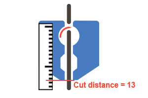
5.4.Cut distance (mm)
The cut distance is the distance from a cut point to outlet hole of a nozzle. This value should be set only by printer manufacturer.
5.5.Fiber restart length (mm)
The fiber restart length is the length of fiber extrusion during restart. This is necessary for the fiber tail to get out of the nozzle. This parameter should be greater than or equal to the cut distance. For Anisoprint Composer this parameter is lagrer than the cut distance for 1-2mm.
5.6.Cut G-code
The cut G-code is the code, that actuates fiber cutting. This value should be set only by printer manufacturer.
5.7.Has cooling fan
The has cooling fan flag is the flag which indicates thar extruder has a nozzle cooling fan.

5.8.Cooling fan index
The cooling fan index is the number of this cooling fan in printer firmware.
6.Profile (Part)
6.1.Use fiber
The use fiber flag is the flag which indicates that parts may be reinforced with fiber.
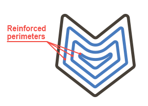
6.2.Generate reinforced perimeters
The generate reinforced perimeters flag is the flag which indicates that the Aura will generate reinforced perimeters for printed parts.
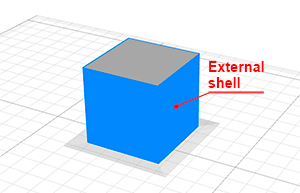
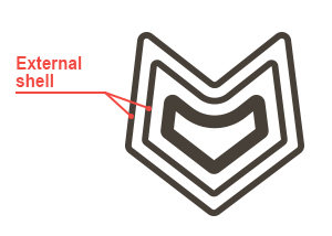
6.3.External shell perimeters count
The external shell perimeters is the number of perimeters which build the plastic external shell – the most precise one.
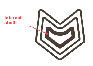
6.4.Plastic perimeters count
The plastic perimeters count is the number of perimeters which build the plastic internal shell. It provides solidity of part surface.
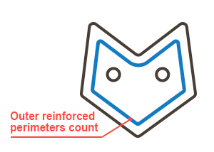
6.5.Outer reinforced perimeters count
The outer reinforced perimeters count is the number of perimeters which will reinforce outer surface(not holes) of a part.
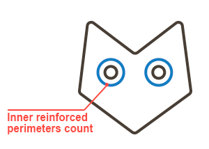
6.6.Inner reinforced perimeters count
The inner reinforced perimeters count is the number of perimeters which will reinforce inner holes (not surface) of a part.
6.7.Plastic perimeters count outside fiber
The plastic perimeters count outside fiber is the number of perimeters between external shell and fiber perimeters.

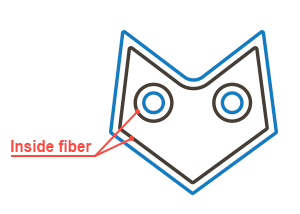
6.8.Plastic perimeters count inside fiber
The plastic perimeters count inside fiber is the number of perimeters between fiber and cellular infill.
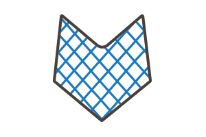
6.9.Fill density (%)
The fill density percent is the percent of filled space inside the shell.
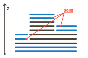
6.10.Top/bottom solid layers count
The top/bottom solid layers count is the number of layers in which solid infill will be generated. The solid infill will be generated in special spots – where a layer contacts with external environment.
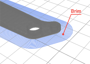
6.11.Generate brim
The generate brim flag is the flag which indicates that the Aura will generate brims for parts. The brim is the extended contour of a part on a first layer. Use brim to prevent part stick-off from table surface during printing process.
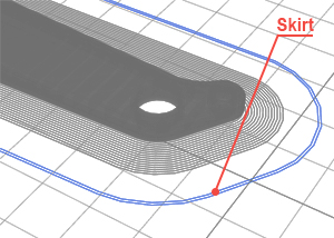
6.12.Generate skirt
The generate skirt is the flag which indicates that the Aura will generate skirts for parts. The skirt is the extended contour of a part on a first layer. Use skirt to stabilize plastic flow in extruder before main printing.
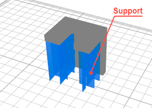
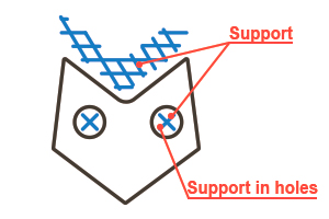
6.13.Generate support
The generate support flag is the flag which indicates that the Aura will generate supports for parts. The support is used to prevent the fall of overhanging parts.
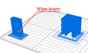
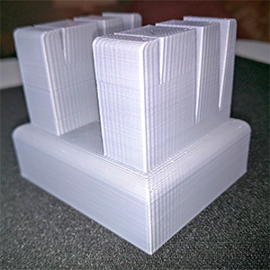
6.14.Generate wipe tower (BETA)
The generate wipe tower flag is the flag which indicates that the Aura will generate wipe tower for parts. The wipe tower is a service part that is being printed at the same time as main parts. The wipe tower is used to clean nozzles on tool change.
7.Profile (General)
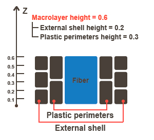
7.1.Macrolayer height (mm)
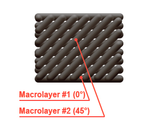
The macrolayer height is the height of a layer package which contains microlayers. The microlayer is the layer which contains one or more print entities with the same height. The macrolayer contains microlayers and its structure is defined by microlayer heights. For example, macrolayer height = 0.6mm, external shell height = 0.2mm, plastic perimeters height = 0.3mm, fiber layer height is always equal to macrolayer height and now it is 0.6mm. Accordinally, in this macrolayer we have 4 microlayers. First on 0.2mm and it has only external shell for printing. Second on 0.3mm and it has only plastic perimeters. Third on 0.4mm and it has only external shell. And the last one on 0.6mm and it has external shell, plastic perimeters and fiber perimeters.
7.2.External shell layer height (mm)
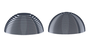
The external shell height is the height of thin plastic layers which build up an external shell of a part. The thinner external shell, the more precise and accurate the part looks.
7.3.Plastic perimeters layer height (mm)
The plastic perimeters layer height is the height of thick plastic shell. Set this value as much as possible to speed up the print process. The thick plastic perimeters make parts more strong. Because plastic perimeters are not visible they can be printed thicker than an external shell to speed up the printing process.

7.4.Infill layer height (mm)
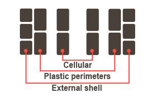
The infill layer height is the height of layers which contain cellular infill. The cellular infill is inside plastic perimeters and leaves an empty space in a part.
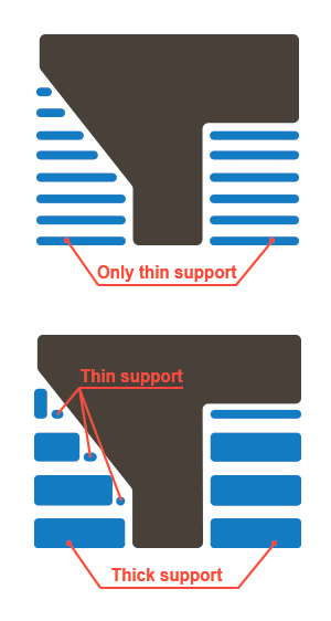
7.5.Thick support layer height (mm)
The thick support layer height is the height of layers which contain thick supports. The thick support is calcalated by intersection of thin support layers. Set thick support layer height as large as possible to speed up the print process.
7.6.Thin support layer height (mm)
The thin support layer height is the height of layers which contain thin supports. Thin supports are generated in the areas which can’t be converted into thick support.
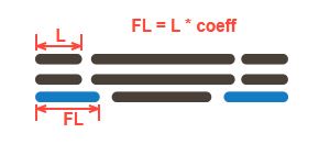
7.7.First layer extrusion width coefficient
The first layer extrusion width coefficient is the extrusion width multiplication factor. It has affect on extrusion width for all entities on first layer and consequently on plastic amount.
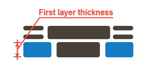
7.8.First layer height (mm)
The first layer height is the height of the first layer. Set this parameter a little bit larger that other microlayers to compensate table relief. The first layer has no microlayers structure as macrolayer and it doesn’t comprise into any macrolayer as other microlayers.
7.9.First layer printing speed (mm/sec)
The first layer printing speed is the speed of printing of all entities at the first layer. You may want to set this value a little slower than average speed on other layers to improve adhesion between parts and a table.
8.Profile (External shell)
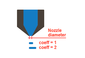
8.1.Extrusion width coefficient
The extrusion width coefficient is the nozzle diameter multiplication factor. That is extrusion width = nozzle diameter * coefficient.
8.2.Printing speed (mm/sec)
The printing speed is the speed which will be applied to external shell printing. Set this parameter to the sufficient minimum to improve surface quality of parts. The slower printing speed, the lower chance to obtain vertical ringing on parts.
9.Profile (Plastic perimeters)
9.1.Extrusion width coefficient
The extrusion width coefficient is the nozzle diameter multiplication factor. That is extrusion width = nozzle diameter * coefficient.

9.2.Printing speed (mm/sec)
The printing speed is the speed which will be applied to plastic perimeters printing. Set this parameter as high as possible to speed up printing process.
10.Profile (Reinforced perimeters)
10.1.Extrusion width (mm)
The extrusion width is the width of composite material (plastic + fiber).
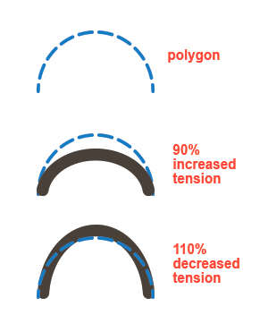
10.2.Fiber feedrate (%)
The fiber feedrate is the percent of full presumed path length. Descrease this parameter to increase fiber tension and increase this parameter to descrease fiber tension.
10.3.Printing speed coefficient
The printing speed coefficient is the multiplication factor which will be applied to fiber print speeds.
10.4.Solid plastic layers above fiber count
The solid plastic layers above fiber count is the number of macrolayers in which solid infill will be generated. This parameter not used as solid plastic layers below fiber, so you may want to use it only for cover up fiber polygons from above.
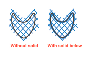
10.5.Solid plastic layers below fiber count
The solid plastic layers below fiber count is the number of macrolayers in which solid infill will be generated. It needs to prevent fiber fall through cellular infill.
11.Profile (Solid infill)
11.1.Extrusion width coefficient
The extrusion width coefficient is the nozzle diameter multiplication factor. That is extrusion width = nozzle diameter * coefficient.

11.2.Printing speed (mm/sec)
The printing speed is the speed which will be applied to plastic infill printing. Set this parameter as high as possible to speed up printing process.
11.3.Fill starting angle (°)
The fill starting angle is the starting angle of infill rotation.
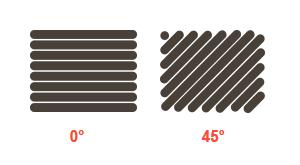
11.4.Fill angle offset (°)
The fill angle offset is the offset angle which is added to current infill rotation angle on each layer. For example, if fill angle offset is 10°, on first macro layer angle is 0°, on second is 10°, on third is 20° etc.
12.Profile (Cellular infill)
12.1.Extrusion width coefficient
The extrusion width coefficient is the nozzle diameter multiplication factor. That is extrusion width = nozzle diameter * coefficient.

12.2.Printing speed (mm/sec)
The printing speed is the speed which will be applied to plastic infill printing. Set this parameter as high as possible to speed up printing process.
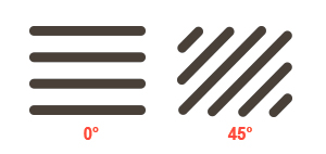
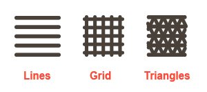
12.3.Fill pattern
Fill pattern. You could choose from three patterns: lines, grid or triangles, depending on your preferences.

12.4.Fill angle (°)
The fill starting angle is the angle of infill rotation.
13.Profile (Brim)
13.1.Extrusion width coefficient
The extrusion width coefficient is the nozzle diameter multiplication factor. That is extrusion width = nozzle diameter * coefficient.

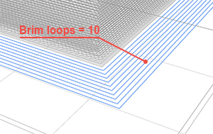
13.2.Loops count
The brim loops count is the number of brim loops around a part. The more loops, the adhesion between parts and a table is stronger.
14.Profile (Skirt)
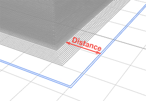
14.1.Distance from part (mm)
The distance from part is the distance between skirt and part.
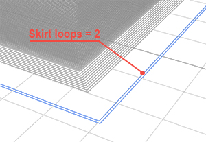
14.2.Loops count
The skirt loops count is the number of skirt loops around a part. Choose the sufficient number to stabilize plastic flow by the end of printing the skirt.
15.Profile (Support)
15.1.Generate support in holes
The generate support in holes is the flag which indicates that support will be generated not only on the outside of part but in holes too.
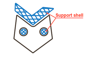
15.2.Generate shell for support
The generate shell for support is the flag which indicates that external shell will be generated for supports.
15.3.Make airgaps
The make airgaps flag is the flag which indicates that air gaps will be generated onto and/or under supports.
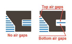
15.4.Top airgap thin layers count
The top airgap thin layers count is the number of layers between the top of a support and the bottom of a part. Choose a value with which support will be easy to tear from a part and supported areas will not fall down because of large distance to a support.
15.5.Bottom airgap thin layers count
The bottom airgap thin layers count is the number of layers between the bottom of a support and the top of a part. Choose a value with which support will be easy to tear from a part and support will not fall down because of large distance to a part.
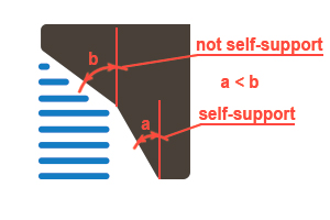
15.6.Max unsupported overhang angle (°)
The max unsopported overhang angle up to which part overhang has no need to be supported. If angle is more than the unsupported angle then supports will be generated. The angle is regarding to vertical axe.
15.7.Fill density (%)
The fill density percent is the percent of filled space inside the support.

15.8.Fill pattern
Fill pattern. You could choose from three patterns: lines, grid or triangles, depending on your preferences.
15.9.Fill angle (°)
The fill angle is the angle of infill rotation.

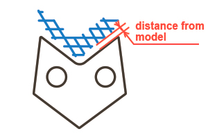
15.10.Horizontal X/Y distance from model (mm)
The horizontal X/Y distance from model is the offset from a part to supports. Set this parameter to a part has no fusion with supports.
16.Profile (Ooze prevention)
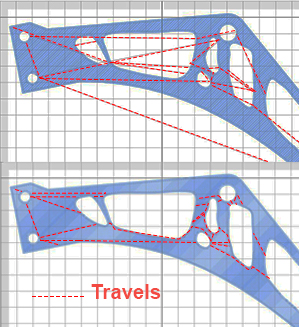
16.1.Avoid crossing borders
The avoid crossing borders flag is the flag which indicates that border crossing minimization mode in on. It means that if it is possible to travel from one print area to another without crossing borders, that path will be chosen instead of direct path with borders crossing . This mode increases print time, but improves external surface quality.
16.2.Do retract only when crossing borders
The do retract only when crossing borders is the flag which indicates that only crossing perimeter travels will have retracts before them. Choose that mode to speed up print process. Plastic that running from nozzle on travels will be all inside a part, so it will not be visible. If you want to do retract before all travels you should uncheck this flag.
16.3.Do retract on changing layers
The do retract on changing layers is the flag which indicates that plastic will be retracted on layer change even if there is no XY movements during change layers.
16.4.Do Z-hop when retracted
The do z-hop when retracted flag is the flag which switches on/off a nozzle z-hop mode when travel has retract. Choose this mode to improve external shell surface quality, but keep in mind that it sligtly slow down print process. Besides, it may produce strings between print areas, but usually it is easier to remove them than plastic drops.
16.5.Do coast before retract
The do coast before retract is the flag which indicates that plastic polygon will have dry (without plastic feeding) segments in the end.
16.6.Do wipe nozzle
The do wipe nozzle flag is the flag which indicates that plastic polygon will have reverse movement after full polygon print has ended.
17.Profile (Other)
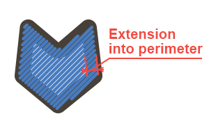
17.1.Infill extension into perimeters
The infill extension into perimeters is the length by which infill penetrate perimeters. Choose the length that provides infills fusion together with perimeters.
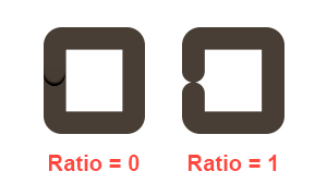
17.2.Perimeter trim ratio
When this parameter is 0 plastic polygon is fully closed. When this parameter is 1, plastic polygon has empty gap that is equal to extrusion width. Choose the value that is differ from 0, if you’ve seen the plastic overextrusions on polygon seam.
17.3.Minimum layer print time (sec)
When this parameter is 0 plastic polygon is fully closed. When this parameter is 1, plastic polygon has empty gap that is equal to extrusion width. Choose the value that is differ from 0, if you’ve seen the plastic overextrusions on polygon seam.