To find out the hardware version, press Maintenance > About printer
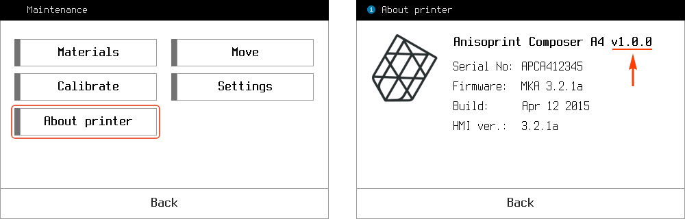
To find out the hardware version, press Maintenance > About printer
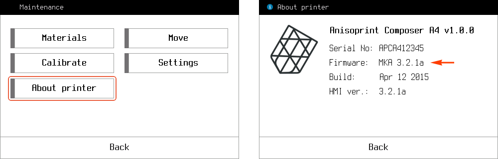
To find out the firmware version, press Maintenance > About printer
Note
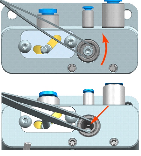
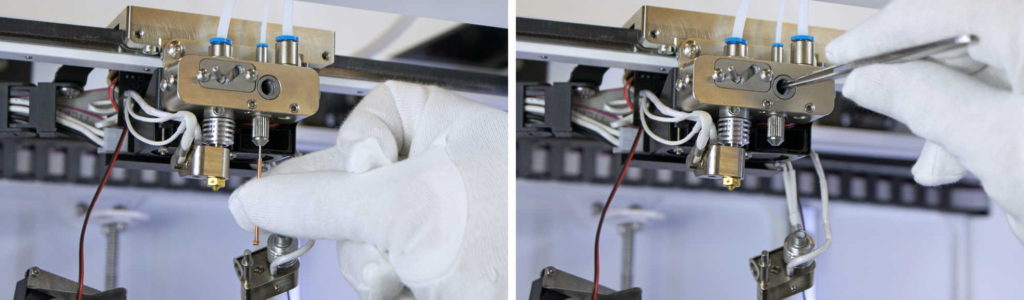
Servo is under voltage and try to keep the torque, at each moment of time. It means that if you try to tighten it with too much force you can burn the servo, please be careful and follow the instruction.
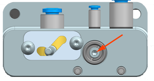
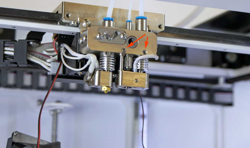
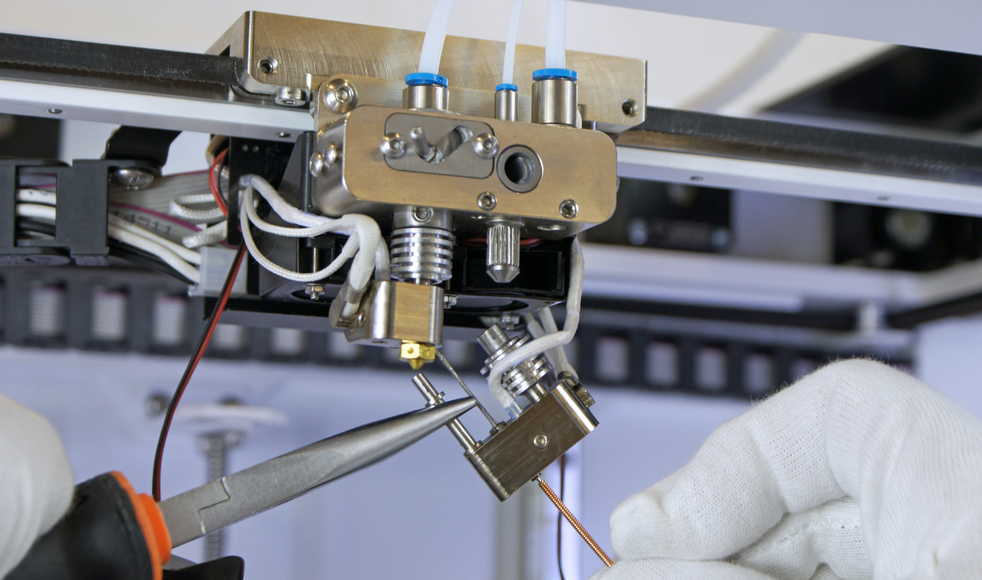
To correct the cutter positioning you need to follow these simple steps:
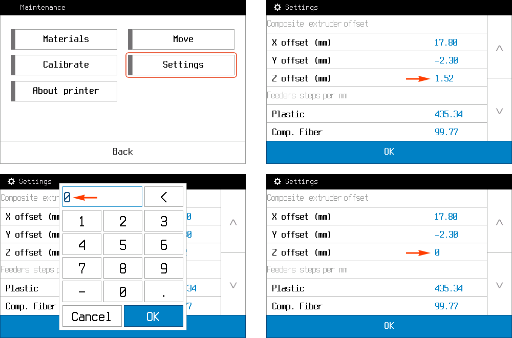
In case of a problem with Z or offsets calibration, it is necessary to check the EEPROM. Operating procedure will be:
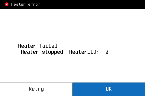
In the case when Сomposer fails to heat one of the extruders, it will gives “Heater failed” error.
To identify the cause of the error, you need to check the heaters. Operating procedure will be:
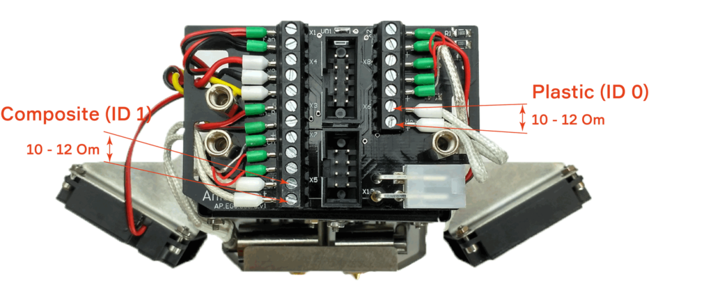
If the measured resistance is close to the correct (10-12 Om), it’s means that the temperature sensor works good. You will need to contact your local distributor or write us on support@anisoprint.com
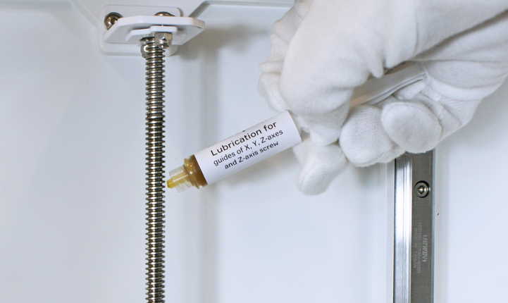
To extend the service life of the Composer CFC Printer, the mechanical parts of the product must be serviced periodically. The
service includes lubrication of moving nodes: guides of X, Y, Z-axes, Z-axis screw and plastic extruder. The delivery package includes
two types of lubricants: for the plastic nozzle and guide axes. lubrication of mechanical parts of the printer is recommended at least
once every six months.
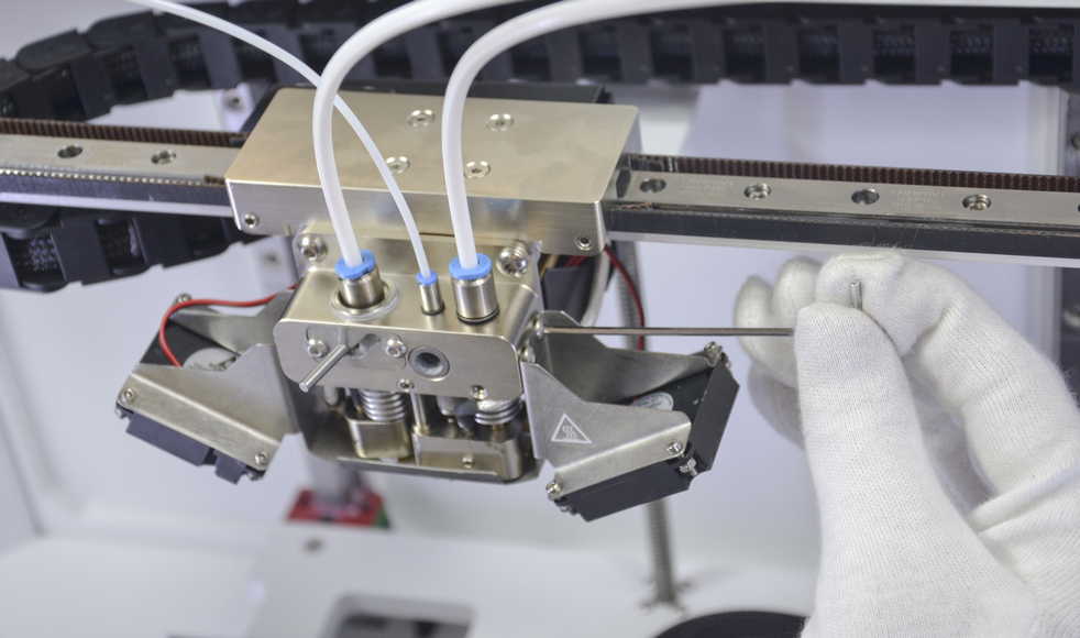
Residual dirt, fiber remnants and degraded plastic are slowly accumulated inside extruder during printing process. To clear the dirt, or remove small fiber pieces from an extruder do the following
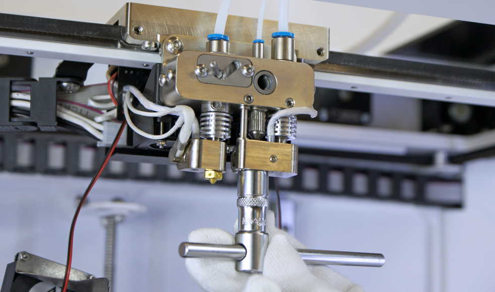
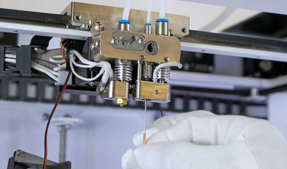
Caution!
Further only In the case of heavy clog.
There are two options to get maximum temperature error on the Composer.
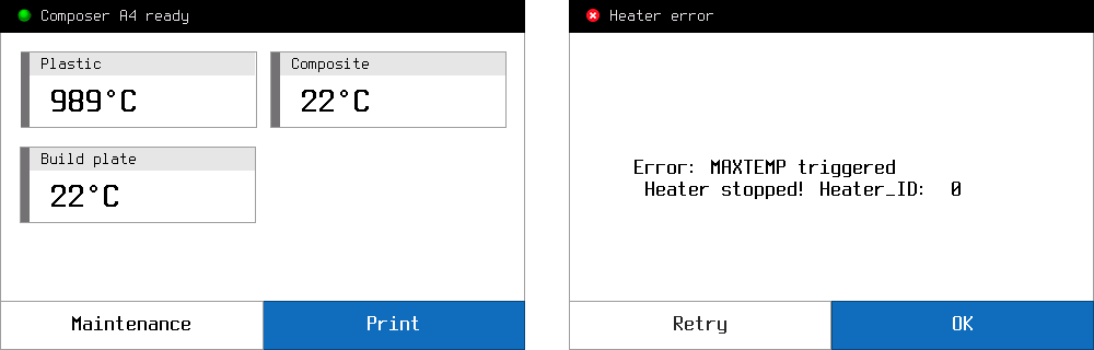
This error comes, when Composer get temperature more than 275 C° from one of the extruders (Heater_ID) or more than 125 C° from buildplate.
Caution!
If you set the temperature in gcode more than 275 С° on extruder or more than 125 С° on buildplate, you will get MAXTEMP error, although the printer will work fine.
To identify the cause of the error, you need to check the temperature sensor. Operating procedure will be:
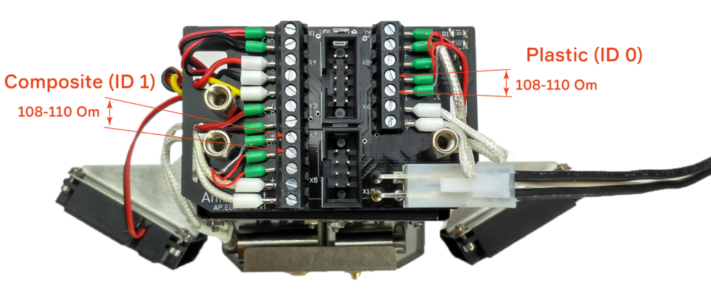
If the measured resistance is close to the correct (108-110 Om), it’s means that the temperature sensor works good. You will need to contact your local distributor or write us on support@anisoprint.com
There are two options to get minimum temperature error on the Composer.

This error comes, when Composer get temperature from one of the extruders (Heater_ID) less than 10 C°
To identify the cause of the error, you need to check the temperature sensor. Operating procedure will be:
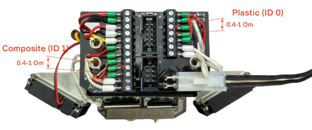
If the measured resistance is close to the correct (0.4-1 Om), it’s means that the temperature sensor works good. You will need to contact your local distributor or write us on support@anisoprint.com