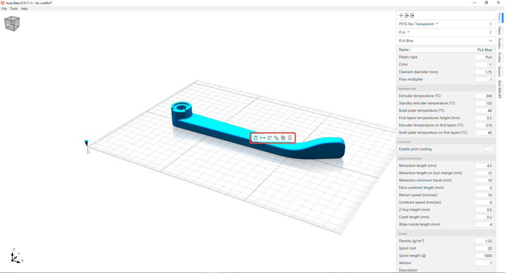
The extruder temperature is the temperature at which plastic will be melted for extruding from a nozzle. You can find an appropriate temperature range on the plastic filament package.
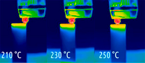
The extruder temperature is the temperature at which plastic will be melted for extruding from a nozzle. You can find an appropriate temperature range on the plastic filament package.
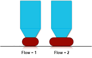
The flow multiplier is a correction factor of plastic extrusion. Vary this parameter if all parts have under- or overextrusion.
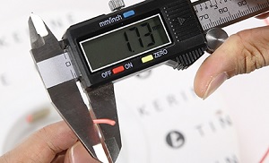
The filament diameter of plastic thread is measured in cross section. Usually it is 1.75mm or 3mm. You can find this value on the package of plastic filament.
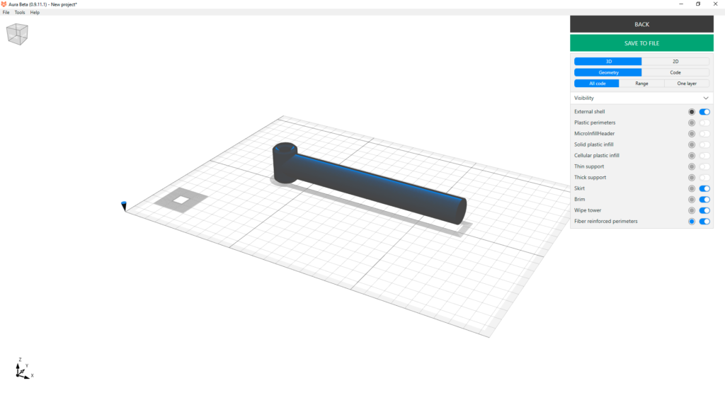
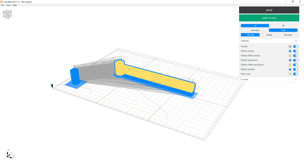
Aura has two print process visualizers – geometry and code explorers. Geometry view helps you to understand how a part will be printed while code explorer shows exact print head trajectories. Geometry viewer shows entities such as external shell, plastic perimeters, micro, solid and cellular infills, supports, fiber perimeters and etc. Code viewer represents entities such as travels, moves, pure extrusions, retracts, moves with fiber etc. In both modes you can switch between 3D and 2D mode, you can observe all layers, layer range or one layer. And you can show or hide individual entities and change their colors. In code mode you can also display and read G-code, in future Aura versions we will add possibility to select G-code lines and highlight appropriate code blocks on the model.
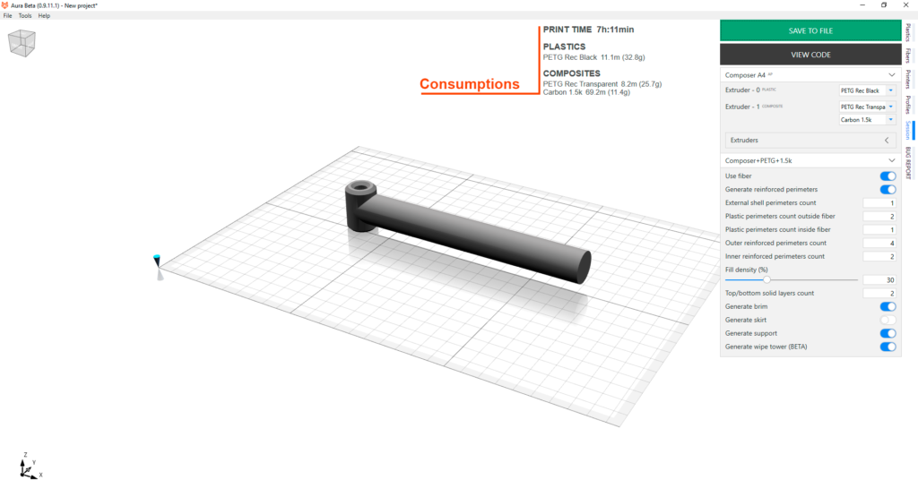
After you’ve configured models and a printing session as you want, press Generate button to generate geometry and translate in to machine code. During process you can Cancel generation with lose of all progress. When generation is successfully finished the printing time and materials consumption information will appear. Materials consumplion is calculated by length and mass. You can Save to file machine code or open code viewer by pressing View code button.
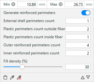
You may want to have non-homogeneous part structure. For example, you may want to reinforce with fiber only bottom and top layers to obtain maximum bending stiffness with small amount of fiber. Or you may want to renforce the bottom layers more than the top. Generally, if you have specific requirements about how the part should be reinforced at different levels, you may achieve the result with layers structure configuration.
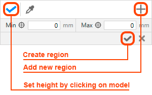
After you press a set layer structure button on the model panel, the window changes it’s state to layer structure settings mode.
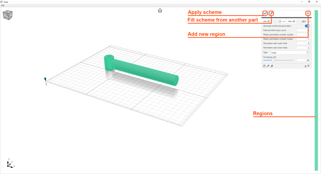
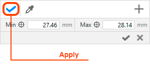
You may copy layer scheme from another model. Just press a button with picker icon and then click on a model from which you want to apply layers structure.
To observe region details and edit region just select it from Regions panel. Configure it’s settings as you need. Keep in mind that regions with same color have same properties and they are connected between themselves. It means, that changes made to one regions will affect other regions with the same color.
After you have finished to configure layup scheme don’t forget to apply changes by pressing Apply button.
After you’ve loaded a model you will see it on a build plate placed at the build plate center. You can select a model by double clicking on it. Double click on empty space will deselect a model. Double clicking on a part calls model panel.
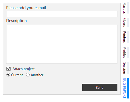
If you’ve encountered bug while working with Aura or you have any suggestion for Aura improvements, please send us a bug report. You can do this from BUG REPORT panel. Please describe a bug and please attach the project that produce this bug. Full bug description and attachment of project that causes the bug will help us to fix it as soon as possible. If you have a question or you want to attach more files, please send it to support@anisoprint.com.
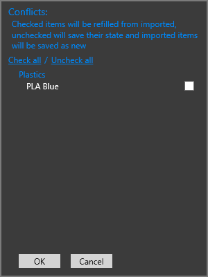
Conflicts dialog emerges if you have conflict with at least one settings item in your project (material or printer or profile). Conflict means that you already have in your Aura settings an item with the same name but with differing settings. For example, you already have Plastics material named “PLA” and flow multiplier = 1. And you want to load the project which contains material “PLA”, and this material has flow multiplier = 1.1. So, this is the conflict and you should solve it before you can continue to work with slicer. You can do it with the Conflict dialog.
Session is the settings aggregator. You should specify printer, profile, materials in extruders, and choose extruder for each print entity. The part settings that you can see at the bottom of session panel can be adjusted individually for each print. Besides, this settings are not taken into account during profile comparison and conflict determination. So if you load a project from a file, this settings are always overrrided without conflict.
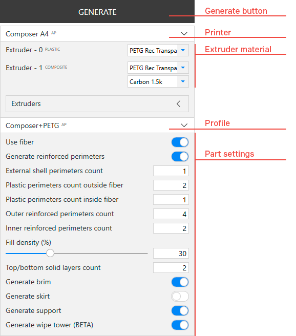
After you’ve configurated session you can press a generate button. If the generate button is disabled check that you have loaded model for slicing and your models have no intersection between themselves.