Plastic nozzle replacement

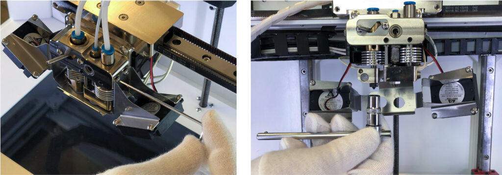
You might need to clean the inner surface of a nozzle – chemically or mechanically, for that, you need to remove the nozzle and install it again. Here are the steps.

  1. Using the 2mm hex key from the tool kit, loosen the side screws of the fan bracket. Remove the fan bracket carefully, it should hang on wires.
  2. Heat the plastic extruder to the printing temperature (270 °C for Smooth PA).
  3. Using the 7 mm socket wrench, unscrew the plastic nozzle from the plastic extruder, do not use too much force to avoid damaging the nozzle.
  4. Clean the nozzle or use a new one.
  5. The nozzle is installed with a special copper washer to avoid leakages of plastic from the extruder. Be sure to remove it from the old nozzle and install on the threaded end of the new one.


CAUTION: all extruder part can be hot!


Network bridge software updating

To update the network bridge software please connect your Composer to the Internet through Wi-Fi. The updates are performed automatically 4 times a day if a new version is available.

Note:

  1. The updates are performed from Ubuntu Snap Store, if your printer is behind a firewall,
    please check the following document to make sure that these network addresses are available for the machine: https://forum.snapcraft.io/t/network-requirements/5147.
  2. If your network can’t have access to the Internet, please contact Support
    (support@anisoprint.com) to receive instructions for an offline update.

WI-FI connection

In order to find out whether your printer supports Wi-Fi, you need to check the version of the printer (see MAIN SCREEN). If the version contains “nw” letters – your printer supports Wi-Fi.

To connect your printer to Wi-Fi follow the instructions below.

  1. Update your Composer firmware to version 1.2.0 or later. You can download the firmware from Anisoprint Support Portal. On the \Guide page you can find instructions for firmware update.
  2. Check the version of network bridge software (see MAIN SCREEN p 7.1).
    • If the NW ver. is n/a please turn the printer off and on and wait for one minute (the network bridge booting process takes about a minute after power on).
    • If the NW ver. is 0.1, please follow additional instructions marked with an asterisk. Also, please update the Network software to the latest version.
  3. To update the network bridge software to the latest version, see NETWORK BRIDGE SOFTWARE UPDATING p 7.11.
  4. Go back to Menu from About Printer screen.
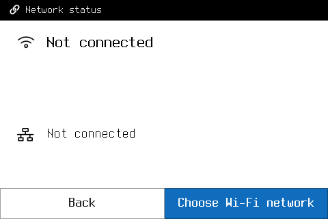
  5. Go to Network -> Connections.
    • For NW v0.1: please wait for 10 seconds before pressing the «Choose Wi-Fi network» button. If the list of networks is empty, please go back and try again.
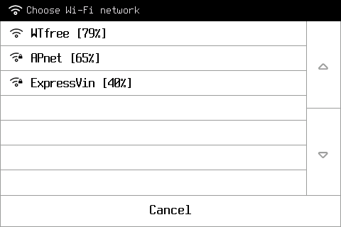
  6. Press Choose Wi-Fi network.
    • For NW v0.1: if the desired network is not on the first page, please wait for 10 seconds before going to the next page by pressing the arrow on the right side of the screen.

       7. Select your Wi-Fi network from a list. If the network is secured, enter the network security key and press OK.

In-situ tuning of printing settings

Some basic operations with the printer are still available during the printing.

After you start the print, the PRINTING screen appears. Here you can pause your print by pressing the PAUSE button, or adjust the printing process by pressing the CONTROL button.

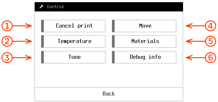
After the print is paused, the print head and buildplate will return to their default positions. Extruders stay hot during the pause. You can see all the control capabilities over the paused print in the picture below.

Here, the following settings are available:
1 — Cancel the print
2 — Cool or heat up extruders and buildplate
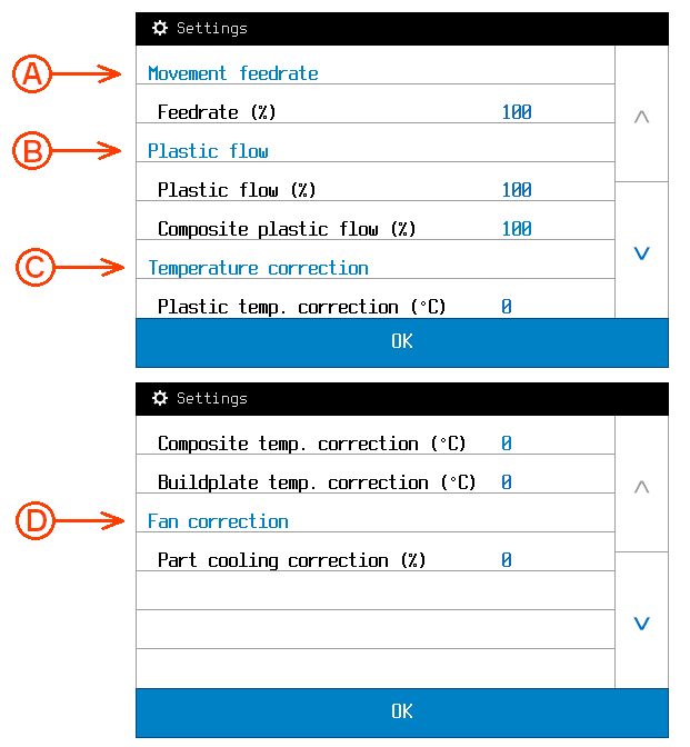
3 — Printing parameters tuning. Here, the following settings are available:

A – Movement feed rate determines printing speed (100% by default, can be varied within a range of 25 to 200%).
B – Plastic flow parameters adjust extrusion coefficients of plastic in a percentage manner. Plastic flow range is from 25 to 150%).
C – Temperature correction value increases or decreases predefined temperature on set increment (0 °C by default, can be varied within a range of -100 to 100 °C). Note that the temperature is limited by 270 °C for extruders and 120 °C for buildplate.
D – Fan correction value increases or decreases predefined fan power (0 % by default, can be varied within a range of -100 to 100%).4 – Axis positioning (see MAIN SCREEN p 7.1)
5 – Loading/unloading materials (see LOADING MATERIALS p 7.3)
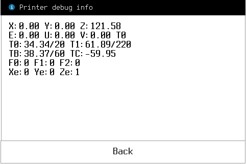
6 – Debug info is service information (for service engineer if required)

Press the RESUME button to continue the print from the stopping point.

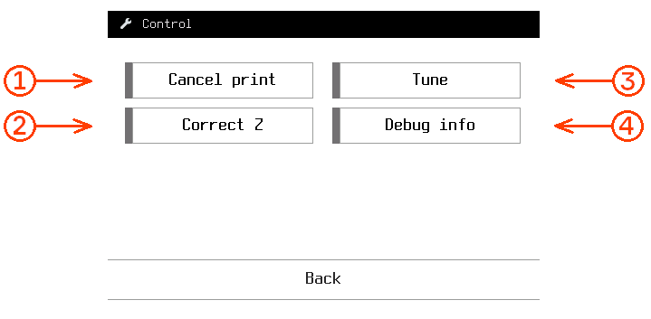
Press the CONTROL button in printing mode to tune the printing process. The screen when the CONTROL button is pressed in the printing mode is shown below.

Here, the following settings are available:

1, 3 and 4 buttons are the same as for paused print
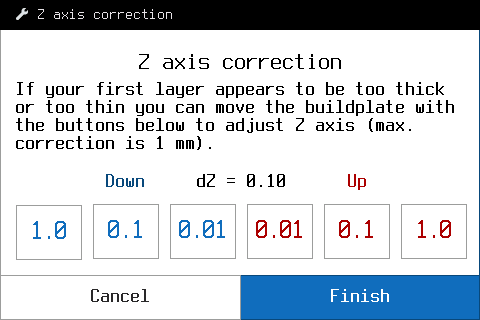
2 – Correct Z. If the first layer of the print is too thick or thin you can move the buildplate up or down by 0.01/0.1/1 mm to achieve the optimum thickness of the first layer. Notice, that this setting does not influence the Z axis calibration.

Test print

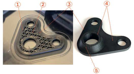
The test part “Wall bracket” introduces you the capabilities of Composer and also serves as a combined quality test. You can find the “Wall bracket” for the particular profile in the Aura Welcome window.

  • Use recommended adhesive for your plastic filament, e.g. Magigoo Original for transparent PETG or Magigoo PA for polyamide (PA).
  • After the print start, both extruders, plastic and composite, start to heat. When the composite extruder reaches the extrusion temperature, the composite nozzle will print a short purge line (composite thread) on the build plate. It must be glued to the surface and look smooth and uniform.
  • After printing the purge line, the machine will start the first plastic layer. Check that the plastic perimeters look the same along the part. The first layer must be nicely glued to the build plate.

1 – Fiber perimeters
2 – Cellular fiber infill
3 – Outer plastic perimeters
4 – Plastic top cover
5 – Plastic shell

  • After several plastic layers, the machine will start the first fiber perimeter and fiber cellular infill. Due to the process features, it may look a bit wobbly, but the layup visual quality will normalize later on. If the fiber goes off trajectory or doesn’t glue to the previous layer, go through the Z OFFSET CALIBRATION procedure p 7.6.
  • During the next plastic-composite cycles, fiber perimeters will be surrounded by plastic ones. Make sure the plastic and fiber perimeters do not intersect and fiber perimeters are laid without displacements.
  • Inspect the printed part paying special attention to side walls quality. Check the surface smoothness visually and compare it to the photo above. In case of poor side walls quality, go through the Z OFFSET CALIBRATION procedure p 7.6.

Congratulations on your first print!

XY offset calibration

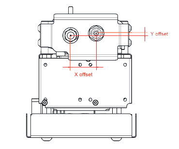
X and Y offsets are the physical distances between the tips of the plastic and the composite nozzles at the Composer print head, shown in the picture below.

You need to go through XY offsets calibration once after composite or/and plastic nozzle replacement. In order to calibrate XY offsets, print the special service code NozzleOffsetTest.gcode from the external memory device supplied with your Composer printer. You can also download it from support.anisoprint.com

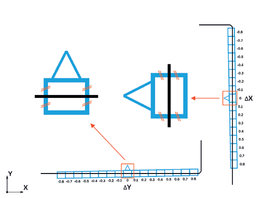
If the XY offsets are well-calibrated, the composite fiber is in the middle of the central cells, like it is shown in the scheme

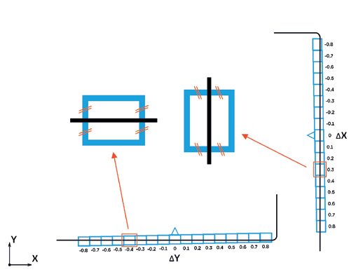
If the composite fiber deviates from the middle position of the central cells, like it is shown in the reference scheme, you need to change your XY offsets values (i.e calibrate it)

In order to calibrate XY offsets, for every axis find the cell where the composite fiber is right in the middle as shown on the reference scheme (right picture). XY adjustment value for each axis is written near the corresponding cell. For the given example it is +0.3 for X offset and -0.4 for Y offset, which means that you need to add +0.3 to the original X offset and -0.4 to the original Y offset.

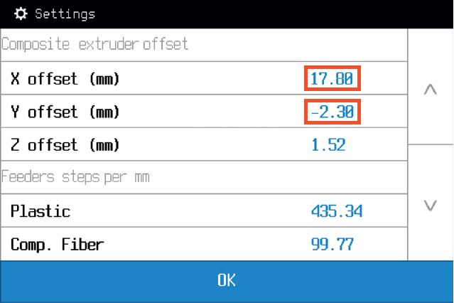
To change these values, go to Maintenance > Settings.

The new offsets will be
17.80 + 0.30 = 18.10 for X offset,
and -2.30 – 0.40 = -2.70 for Y offset.


After adjusting the offsets, reprint the offset test and make sure that composite fiber is in the middle position for both X and Y central cells.

Z offset calibration

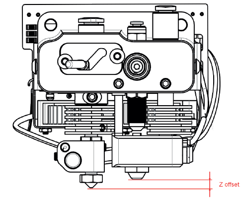
Z offset defines the relative position of the composite nozzle with respect to the plastic nozzle about Z-axis.

If the composite nozzle tip scratches the buildplate or previous layers, or the quality of vertical walls of your model is insufficient due to improper plastic layup, go through this procedure. Also, it is recommended to go through this procedure every time you replace the composite or/and the plastic nozzle.

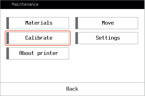
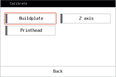
On the screen of the printer, press Maintenance > Calibrate > Printhead > Comp. Z offset. and go through the built-in calibration procedure by following the instructions on the screen.

Z-axis calibration

The distance between the buildplate and the plastic nozzle tip is quite an important parameter affecting the quality of your prints. You need to go through this procedure every time you replace the plastic nozzle or if you faced some issues with laying out the first layer of the print.

Press Maintenance > Calibrate > Z axis and follow the instructions. You will be asked to use a sheet of 80gsm paper to fine-tune the gap between the nozzle tip and the buildplate.

Print any file to verify the results of the calibration, paying attention to the brim and the first layer layup. You can tune the first layer height during the print, see IN-SITU TUNING OF PRINTING SETTINGS p7.9.

It is recommended to calibrate the Z offset right after the Z-axis calibration.

Buildplate calibration

Your Composer had already been pre-calibrated before shipping, but due to transport vibrations, it could be uncalibrated. Thus, you may need to go through the entire calibration procedure after the printer installation.

NOTICE: Clean and preheat the nozzles and the buildplate to its printing temperatures before all the calibration procedures (buildplate, Z axis, Z-offset) to prevent incorrect calibration.


You need to go through the buildplate calibration procedure after any changes affecting the positioning of the buildplate, e.g. shaking or moving the printer. While printing a large part occupying the whole buildplate area, you can notice layer thickness varies from one end of the part to another, which as well means the buildplate requires recalibration.

To start the calibration, go to the main screen, press Maintenance >Calibrate > Buildplate. Follow the instructions. First, you will be asked to set the plastic nozzle in approximately 1 mm from the buildplate. The first of 3 points is to be set through the calibration menu,
the left and right corners are tuned manually by adjusting the regulation screws. Second, the procedure is to be repeated for fine-tuning, this time using a sheet of 80gsm paper to set the lowest possible gap between the nozzle and the buildplate. The paper must be sliding in the gap with slight friction.

It is recommended to calibrate the Z-axis right after the buildplate calibration.

Loading materials

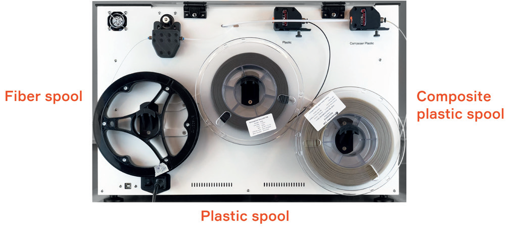
1. Take the 3 spools (plastic, composite plastic, and fiber) out of package and place them
onto the holders.

2. On the Composer screen, click Maintenance > Materials > and choose the material you want to load. Follow instructions on the screen.

NOTICE: Plastic can leak out of the composite heat block inlet during plastic filament loading in the composite extruder. Just remove the leaked plastic with tweezers to prevent dripping of the plastic on the printed part.